Parts Machining Guide: From Drawing Review to Final Inspection
For buyers sourcing custom components, parts machining is not just about cutting metal to shape. It is a controlled engineering workflow that starts with drawing review and ends with final inspection, shipment approval, and repeat production readiness. Whether the part is a simple bracket, a precision shaft, a valve body, or a complex housing, the success of cnc machining services depends on how well the supplier understands geometry, tolerance logic, material behavior, production scale, and inspection priorities before the first chip is cut.
From the buyer perspective, the key question is not only whether a part can be machined, but whether it can be machined reliably, economically, and repeatedly. That is why a strong parts machining process includes drawing review, process planning, fixture design, machining route definition, in-process control, and final validation. When these steps are done properly, lead time becomes more predictable, quality becomes more stable, and rework risk is greatly reduced. When they are ignored, even a part that looks simple on paper can become expensive, late, or inconsistent in production.
What Parts Machining Means from a Buyer Perspective
Parts machining refers to the controlled removal of material from raw stock such as bar, plate, billet, or tube to create the final component geometry required by the drawing. In modern manufacturing, this is usually done through CNC-controlled milling, turning, drilling, boring, or grinding operations. Buyers usually care less about the machine model itself and more about the final outcome: dimensional accuracy, surface quality, lead time stability, and whether the supplier can support both sample builds and repeat orders.
A reliable machining supplier translates a drawing into a manufacturing plan. That includes identifying which dimensions are function-critical, deciding which operations must be combined or separated, determining how the part should be clamped, and selecting the inspection method that verifies the part without slowing production unnecessarily. In other words, machining quality is built long before the machine spindle starts rotating.
Step 1: Drawing Review Is the Foundation of Parts Machining
The first stage of any strong parts machining workflow is drawing review. This is where the machining team checks whether the geometry is manufacturable, whether the tolerances are realistic, whether the datum structure is clear, and whether any surface finish or post-treatment requirements will affect final dimensions. A proper drawing review also looks for hidden risks such as deep narrow pockets, long unsupported walls, burr-sensitive edges, thin sections, or hole positions that may be difficult to inspect consistently.
From a buyer standpoint, drawing review is where many cost and quality problems are prevented. If a supplier notices that only three dimensions actually require ±0.01 mm while the rest can stay at ±0.05 mm, the quote and cycle time can improve significantly. If a threaded hole is too close to a wall or a deep drilled feature creates chip evacuation risk, this can be flagged before production starts. A careful drawing review also helps determine whether the part is best handled through general cnc machining services, specialized CNC turning, or dedicated CNC drilling support.
Drawing Review Focus | Why It Matters | Buyer Benefit | Typical Risk if Ignored |
|---|---|---|---|
Critical dimensions | Defines what truly controls function | Better cost-to-quality balance | Overmachining or unnecessary scrap |
Datum structure | Controls setup logic and inspection repeatability | More stable assembly fit | Inconsistent measurement results |
Hole and thread layout | Affects tool access and drill stability | Lower risk of broken tools or misalignment | Position errors and rework |
Wall thickness and rigidity | Influences deformation during machining | Higher dimensional stability | Warping, chatter, or surface defects |
Finish and coating requirements | Can change size and cosmetic outcome | Cleaner final delivery planning | Out-of-tolerance after finishing |
Step 2: Process Planning Converts the Drawing into a Machining Route
Once the drawing is reviewed, the next stage is process planning. This is where the supplier determines the operation sequence, machine type, tool strategy, setup count, and whether roughing, semi-finishing, and finishing should be separated. Process planning also considers material type, expected batch quantity, and the balance between cycle time and process capability.
For example, an aluminum housing with multiple pockets and drilled holes may be planned around high-efficiency milling first, then drilling and tapping, then deburring and cosmetic finishing. A stainless shaft may begin with saw cutting, proceed to rough turning, finish turning, threading, and final inspection, with grinding added if roundness or sealing surfaces require tighter control. A good plan reduces idle machine time, protects tolerances, and avoids unnecessary part handling.
This planning stage becomes even more important when moving from prototyping to mass production. Prototype machining prioritizes flexibility and speed, while mass production requires repeatable fixturing, tool-life management, and stable inspection intervals. A supplier that plans for both phases early can help buyers avoid a common mistake: approving a prototype route that cannot scale efficiently later.
Step 3: Fixture Design Controls Repeatability and Stability
Fixture design is one of the least visible but most important steps in parts machining. A fixture determines how the part is located, clamped, supported, and referenced during each operation. Poor fixturing can allow vibration, distortion, positional drift, or inconsistent datum transfer. Good fixturing improves repeatability, shortens setup time, and stabilizes dimensions across a batch.
Different part types need different fixture strategies. Thin-wall housings often require broad support areas to prevent deformation during milling. Long shafts need stable axial support during turning. Small precision parts may require soft jaws or custom nests to prevent marking while maintaining alignment. In many production programs, fixture design directly affects both lead time and yield rate. Investing time in fixturing is often cheaper than dealing with recurring scrap or secondary correction work later.
Part Type | Typical Fixture Need | Main Challenge | Control Objective |
|---|---|---|---|
Flat plate or bracket | Rigid clamping with accurate locating pins | Maintaining flatness after release | Stable datums and surface integrity |
Thin-wall housing | Full-area support or vacuum-style support | Wall deflection during cutting | Reduce distortion and chatter |
Shaft or pin | Soft jaws, centers, or steady rest support | Concentricity and runout control | Hold rotational accuracy |
Valve block or manifold | Multi-face indexed fixture | Hole-to-hole positional accuracy | Reduce cumulative setup error |
Small precision component | Custom nest or micro-clamp fixture | Part marking and unstable gripping | Protect appearance and repeatability |
Step 4: The Machining Stage Varies by Part Shape
Not all machined parts should follow the same route. Part geometry strongly influences which process is most efficient and which risks must be controlled. Buyers who understand this can better evaluate quotations and lead time estimates from suppliers.
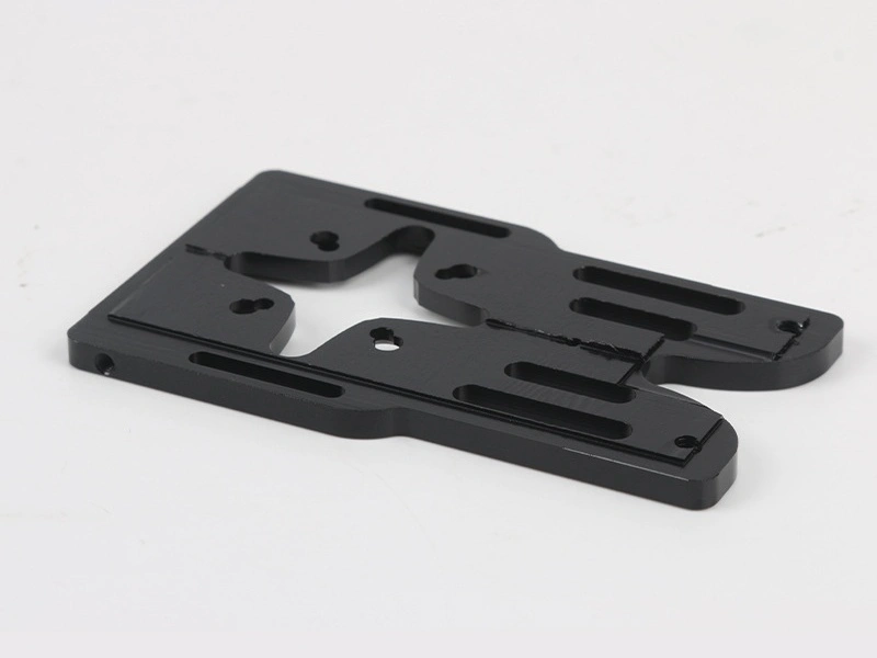
Prismatic Parts
Prismatic parts such as brackets, bases, housings, and blocks are usually dominated by milling operations. These parts often include pockets, slots, tapped holes, counterbores, and machined faces. The main concerns are flatness, perpendicularity, wall rigidity, and maintaining positional accuracy across multiple surfaces. If the part has many hole features, supplementary CNC drilling strategies become important for cycle-time control and consistent hole quality.
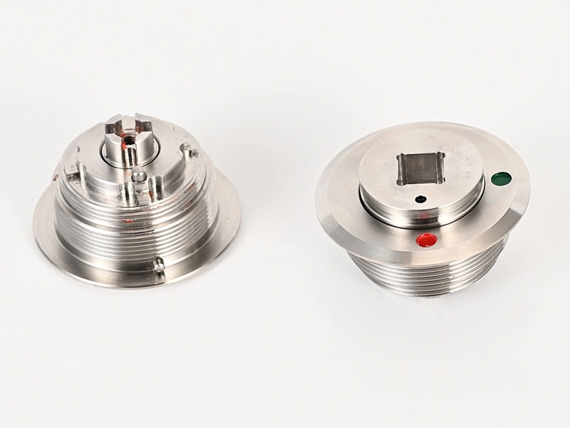
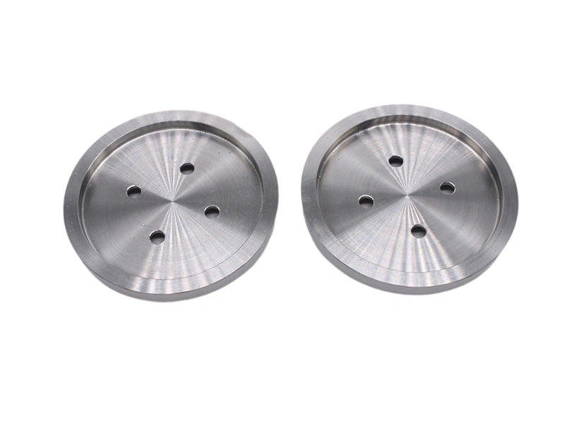
Rotational Parts
Rotational parts such as shafts, pins, bushings, nozzles, and sleeves are usually better suited to CNC turning. These parts rely on concentricity, diameter control, thread quality, and surface finish on cylindrical features. Turning is usually more efficient than milling for axis-symmetric geometry and provides better control over coaxial relationships when the machining route is set up correctly.
Hole-Intensive Parts
Some components are defined primarily by their hole network rather than their outer profile. Manifolds, fluid blocks, fixtures, and structural connection parts often fall into this category. In these cases, the drilling sequence, tool access direction, hole depth-to-diameter ratio, and burr control become major concerns. A machining route that looks efficient on the outside can still fail if the hole-making plan is weak.
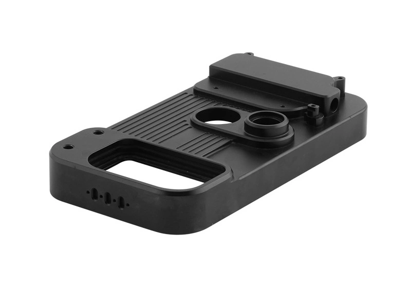
Complex Multi-Face Parts
Parts with features on multiple faces often require several setups, indexed fixturing, or more advanced machining strategies to maintain relative positional accuracy. Here, setup reduction is a major productivity goal because every extra repositioning introduces potential error. Buyers should pay close attention to how the supplier plans datum transfer and whether critical faces are completed in one clamping sequence whenever possible.
Part Geometry | Primary Process | Main Quality Focus | Common Risk |
|---|---|---|---|
Prismatic block or housing | Milling plus drilling | Flatness, pocket accuracy, hole position | Wall deformation or setup mismatch |
Shaft or sleeve | Turning | Roundness, runout, thread consistency | Concentricity drift or tool wear marks |
Manifold or valve body | Drilling, milling, tapping | Hole alignment and sealing surfaces | Cross-hole error or burr contamination |
Thin-wall enclosure | Milling with controlled fixturing | Dimensional stability and cosmetic finish | Deflection, chatter, or local warping |
Multi-face precision part | Multi-setup machining | Datum transfer and true position | Cumulative setup error |
Step 5: Inspection Confirms the Part, Not Just the Process
Inspection is the stage where machining performance is verified against the drawing and buyer expectations. A good inspection plan does not measure everything at the same intensity. It focuses on critical dimensions, mating interfaces, sealing surfaces, hole locations, threads, and appearance-sensitive areas. General dimensions may be checked through standard shop inspection, while high-risk features may require CMM verification, bore gauges, surface roughness measurement, or dedicated thread inspection.
From the buyer perspective, final inspection is important because it connects production reality to assembly performance. A part can pass basic spot checks and still fail in actual use if the wrong dimensions were prioritized. That is why the best suppliers align inspection to function. If a bore must seal, it should be measured like a sealing feature. If a shaft must run at high speed, runout and roundness become more important than cosmetic face milling marks. Inspection is not just documentation. It is the final protection against field failure and return claims.
Lead Time, Quality Control, and Rework Risk
Lead time in parts machining is influenced by more than machine availability. Material stock condition, fixture readiness, setup count, inspection complexity, and finishing requirements all affect the schedule. A simple turned part from standard bar stock can move quickly. A complex multi-face stainless component with multiple threaded holes, tight positional tolerances, and special surface treatment will take longer because more control points are involved.
Quality control and rework risk are closely tied to process discipline. Rework often comes from preventable issues such as poor datum planning, insufficient fixture support, tool wear not being monitored, or finishing allowances not being built into the machining route. Rework is costly not only because it consumes labor, but because it can delay shipment, distort capacity planning, and undermine confidence in repeat orders. For buyers, the best supplier is usually not the one with the lowest initial quote, but the one with the clearest process logic and the lowest probability of hidden failure.
Production Factor | Impact on Lead Time | Impact on Quality | Rework Risk if Poorly Managed |
|---|---|---|---|
Material readiness | Can delay project start | Affects stability and machinability | Wrong stock may force remake |
Fixture preparation | Adds front-end setup time | Improves repeatability | Weak clamping causes dimensional drift |
Toolpath and setup planning | Determines total cycle time | Controls consistency across operations | Poor sequencing causes scrap or delay |
Inspection depth | Adds verification time | Protects shipment quality | Missed defects reach customer |
Post-processing coordination | Can extend delivery window | Affects final size and appearance | Out-of-tolerance after finish |
How Parts Machining Scales from Prototype to Production
A good machining supplier should support both early validation and scaled manufacturing. In the prototyping phase, the focus is usually on speed, geometry verification, and design adjustment. Buyers may accept a more manual route as long as the part is delivered quickly and the engineering feedback is reliable.
In mass production, the priorities change. Fixture life, tool wear control, repeat inspection plans, and stable process documentation become much more important. That transition should be planned early so that prototype success does not create false confidence in a route that is too slow or unstable for volume production. A supplier who understands both stages can help buyers move from first article to long-term supply without a major process reset.
Conclusion: Parts Machining Is a Controlled System, Not a Single Operation
From a buyer viewpoint, parts machining is a full manufacturing system built around drawing review, process planning, fixture design, machining execution, and final inspection. Different part shapes require different process routes, and successful delivery depends on how well those routes are matched to tolerance demands, lead time targets, and production scale. When these elements are managed well, buyers get predictable delivery, lower rework risk, and more stable part quality across every batch.
If you are evaluating suppliers for custom parts machining, the most practical next step is to review your drawings, key tolerances, annual volume, and inspection priorities with an experienced team that can support the full route from quoting to delivery. For projects that need reliable cnc machining services and a scalable path from prototype to repeat supply, starting with the right main service page is the fastest way to move forward.
FAQ
What should buyers check first during drawing review for machined parts?
How does part shape affect the choice between milling, turning, and drilling?
Why is fixture design so important for repeat machining quality?
What factors most often increase lead time or rework risk in parts machining?
How should a machining process change when moving from prototyping to mass production?