How Do Engineers Choose the Right Machining Process for Different Types of Parts?
How Do Engineers Choose the Right Machining Process for Different Types of Parts?
Engineers choose the right machining process by starting from the part geometry, functional features, material, tolerance requirements, and surface finish targets rather than choosing a machine type first. In most real manufacturing projects, the question is not whether a part should be made only by milling, turning, drilling, or grinding. The real question is which process should create each critical feature in the most stable, economical, and accurate way.
For example, CNC milling is usually preferred for flat faces, pockets, slots, side features, and multi-face geometry. CNC turning is best for cylindrical parts such as shafts, sleeves, pins, and concentric stepped diameters. CNC drilling is used for through holes, blind holes, bolt patterns, and thread-preparation holes, while CNC grinding is chosen when the part needs tighter final size control, lower roughness, or more accurate contact surfaces. In complex precision parts, engineers often combine several of these processes in one route because no single machining method can efficiently create every feature at the same quality level.
1. Start with Part Geometry, Because Shape Determines the Primary Process
The first decision usually comes from the basic shape of the part. If the part is primarily prismatic, block-like, plate-like, or requires multiple flat surfaces and pocket features, milling is usually the primary process. If the part is mostly rotational, symmetric around a center axis, or defined by outside diameters, inside diameters, grooves, shoulders, and end faces, turning is usually the starting point.
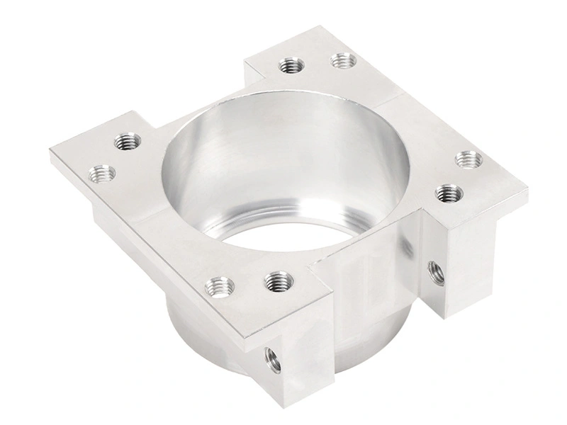
This distinction matters because the wrong primary process increases setup count, reduces efficiency, and makes tolerance control harder. A rectangular aluminum housing with mounting faces, internal cavities, and side holes is naturally a milling part. A stainless steel shaft with stepped diameters, grooves, and threaded ends is naturally a turning part. Good engineers align the process with the dominant geometry first, then assign secondary operations to the remaining details.
Part Geometry Type | Most Suitable Primary Process | Main Reason |
|---|---|---|
Plate, block, bracket, housing | Best for flat surfaces, pockets, slots, and multi-face features | |
Shaft, pin, sleeve, bushing | Best for rotational symmetry and concentric diameters | |
Hole-dominant feature set | CNC drilling as secondary or dedicated operation | Efficient for repeated axial and patterned hole creation |
Critical bearing or sealing surfaces | CNC grinding as finishing process | Improves tolerance, roundness, and surface finish |
2. When Do Engineers Choose CNC Milling?
CNC milling is chosen when the part requires planar surfaces, side walls, cavities, slots, pockets, counterbores, bolt patterns, complex external contours, or features on multiple faces. It is especially useful for brackets, housings, plates, covers, manifolds, heat sinks, and structural components where flatness, perpendicularity, pocket depth, and positional accuracy between faces matter.
Milling is also the preferred process when engineers need flexibility in creating many different feature types on one part. A milled component can include mounting surfaces, shallow and deep pockets, tapped holes, side slots, chamfers, and contour geometry in one integrated setup plan. For parts that are not rotationally symmetric, milling is usually the backbone of the process route.
3. When Do Engineers Choose CNC Turning?
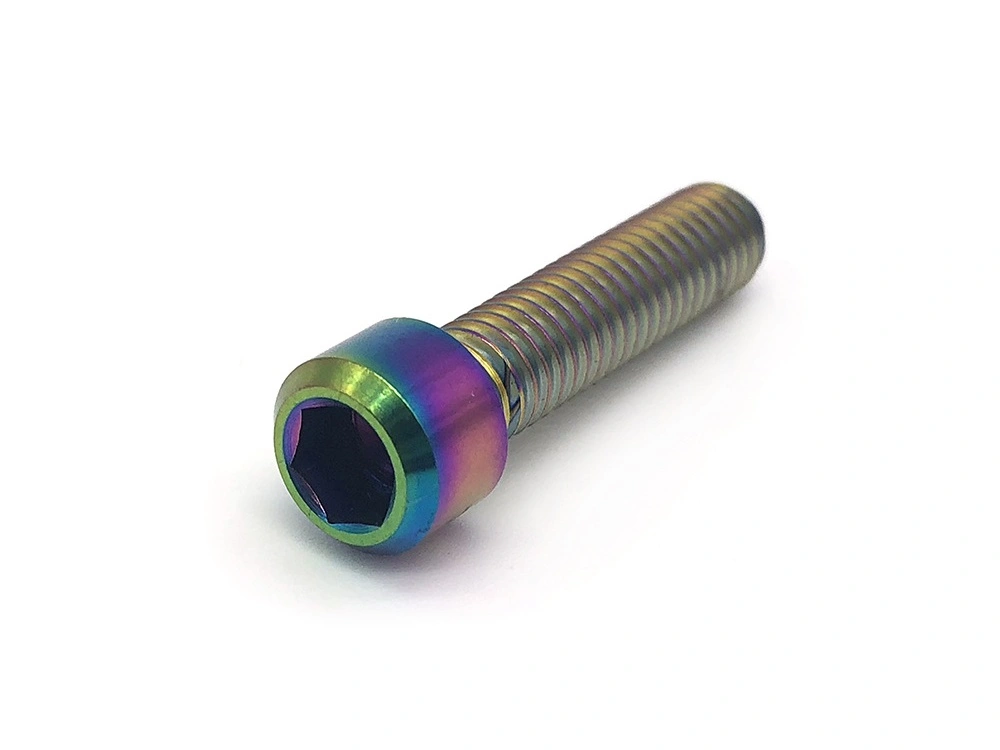
CNC turning is chosen for parts whose key geometry is cylindrical or concentric. Typical examples include shafts, pins, valve bodies, bushings, sleeves, threaded studs, spacers, bearing journals, and stepped mechanical connectors. Turning is highly efficient for creating outside diameters, inside diameters, shoulders, grooves, tapers, chamfers, and axial symmetry with strong concentricity control.
Engineers prefer turning when roundness, coaxiality, and diameter consistency are critical. If a feature can be formed by rotating the workpiece rather than moving around it face by face, turning is often faster and more stable than trying to reproduce the same shape through milling. It is also usually the most practical process for long shafts and turned mechanical components where diameter relationships define function.
4. When Do Engineers Choose CNC Drilling?
CNC drilling is chosen when the part needs through holes, blind holes, pilot holes, bolt-circle patterns, cross holes, or thread-start holes. Drilling is often not the primary process of the whole part, but it is one of the most important feature-making steps in precision machining because holes affect assembly, fastening, fluid flow, alignment, and location accuracy.
Engineers select drilling when hole diameter, depth, spacing, and repeatability matter. In many cases, drilling is followed by reaming, tapping, counterboring, countersinking, or boring depending on the final function. For example, a bracket may be milled for its shape but drilled for mounting holes and thread preparation. A turned shaft may still need cross holes or center drilling. Drilling therefore works as a feature-specific process integrated into broader machining routes.
Feature Type | Preferred Process | Why |
|---|---|---|
Flat faces and pockets | Controls planar geometry and cavity detail efficiently | |
Outside and inside diameters | Best for concentric cylindrical features | |
Through holes and blind holes | Fast and repeatable hole generation | |
Critical final contact surfaces | Higher finish quality and tighter dimensional control |
5. When Do Engineers Choose CNC Grinding?
CNC grinding is chosen when the part requires better surface finish, tighter final size, improved roundness, or more accurate contact behavior than milling or turning can economically provide on their own. This is common for bearing seats, guide diameters, sealing faces, hardened shafts, precision sleeves, and wear surfaces.
Grinding is usually not used to create the entire part from raw stock. Instead, it is a finishing step applied only to selected critical features after milling or turning has already generated the basic geometry. Engineers choose grinding when function depends on the surface itself, such as low-friction sliding, precise bearing fit, or stable sealing under load.
6. Which Process Is Best for Holes, Slots, Threads, and Mating Surfaces?
Different feature types point naturally to different machining methods. Holes are most commonly created by drilling, then refined if needed by reaming, boring, or thread processing. Slots are usually milled because milling gives good control over width, depth, and positional relation to other faces. Threads may be created after drilling through tapping, thread milling, or turning depending on the orientation and size of the thread. Mating surfaces such as mounting faces, sealing planes, and reference datums are usually milled first and may be ground later if surface quality or final fit is highly critical.
This feature-based approach is how engineers prevent overprocessing. They do not grind every face if only one sealing zone truly needs it. They do not turn a non-rotational housing just because it includes one round bore. Instead, they match each feature to the process that can make it with the best balance of cost, quality, and reliability.
Feature | Typical Best Process | Common Follow-Up |
|---|---|---|
Hole | Reaming, tapping, boring, countersinking | |
Slot | Finishing pass for width or depth control | |
External thread on shaft-like part | Thread finishing or inspection verification | |
Internal thread in prismatic part | Drilling plus tapping or thread milling | Deburring and thread gauge check |
Mating or sealing surface | Surface finish refinement if required |
7. Why Are Complex Parts Usually Made with Combined Processes?
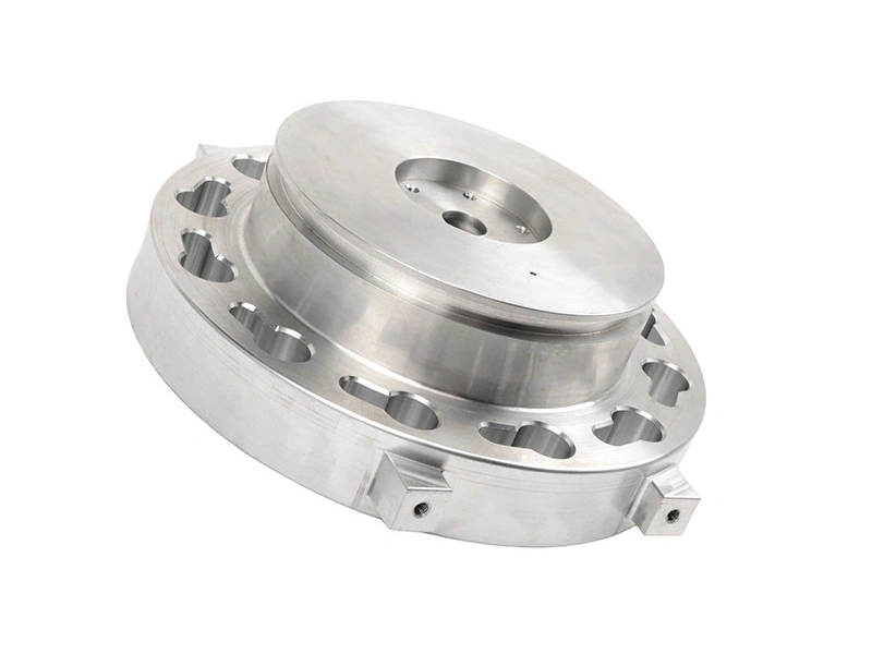
Most precision parts are not pure milling parts or pure turning parts. Complex components often include both rotational and prismatic features, along with holes, threads, tight bores, and finished contact surfaces. That is why engineers usually build a combined process route instead of forcing everything into one method.
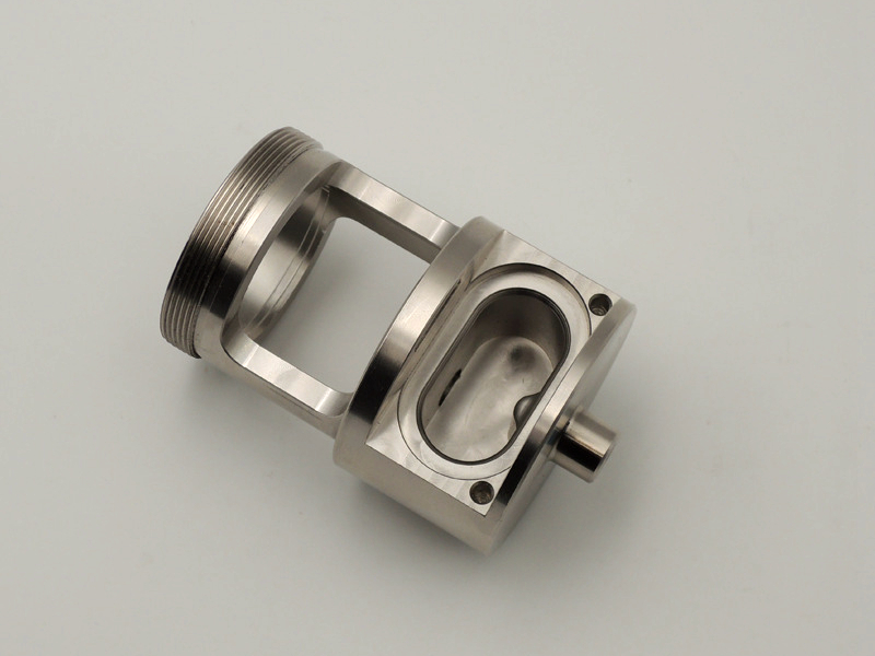
For example, a fluid connector body may begin as a turned blank to form its outside diameters and concentric shoulders, then move to milling for flats and wrench features, then to drilling for cross holes, and finally to grinding if a sealing diameter needs extra refinement. A robotic bracket may be milled for its shape, drilled for mounting points, and ground only on a critical reference face. Combination processing is normal because it balances efficiency with precision.
8. How Do Engineers Balance Cost and Quality When Choosing the Process Route?
Engineers do not simply choose the process that can make the feature. They choose the process that can make it consistently and economically. A feature may be technically possible by milling, but if turning can achieve better concentricity faster, turning is the better choice. A face may be acceptable after milling, but if the part depends on low-friction sealing, grinding may be justified only on that one area.
This means the process route is built around critical-to-function features. General geometry is made with the most efficient primary process, while only selected features receive additional refinement. This approach controls cycle time and inspection cost without compromising quality where it matters.
9. Practical Engineering Selection Guide
If the part mainly has... | Preferred Starting Process | Main Reason |
|---|---|---|
Flat faces, pockets, slots, and side geometry | Best for multi-face prismatic geometry | |
Rotational diameters and concentric shoulders | Best for cylindrical symmetry and diameter control | |
Axial or patterned holes | Efficient hole creation and repeatability | |
Critical final bearing or sealing surfaces | Superior final size and surface control | |
Mixed geometry with several functional feature types | Combined process route | Most complex parts need more than one machining method |
10. Summary
In summary, engineers choose the right machining process by matching the process to the part’s geometry and functional features. Milling is best for flats, pockets, slots, and multi-face parts. Turning is best for cylindrical and concentric features. Drilling is used for holes and thread-preparation features. Grinding is chosen when critical surfaces need better final precision or lower roughness.
Most importantly, complex precision parts are usually made through a combination of processes rather than a single method. The best process route is the one that creates each hole, slot, thread, and mating surface in the most stable and economical way while still meeting the part’s functional requirements.