CNC Medical Parts Manufacturing: Materials, Cleanliness, and Precision Requirements
CNC medical parts manufacturing requires the exact material and condition, feature-level precision, final surface and cleanliness state, verification method, and delivery responsibility to be defined as one production plan. In the medical device industry, a dimensionally conforming part can still fail if the alloy state is wrong, a critical edge carries a burr, residue remains in a blind feature, or a later finish changes a fit. Effective CNC medical parts manufacturing therefore connects design inputs to material control, machining, finishing, cleaning, inspection, packaging, and records.
Buyers should start with the component's function, contact path, operating environment, mating interfaces, cleaning or sterilization exposure, and delivered state. Those inputs determine the grade, heat treatment, datum scheme, critical characteristics, surface specification, contamination limits, and evidence required at release. A supplier quote based only on a model and material family cannot reliably price these controls. The RFQ should include the released drawing, exact material specification, final treatments, acceptance methods, sampling, traceability, packaging, and responsibility boundaries. Undefined edges, cleanliness, or inspection state should be resolved before quoting because each omission can change tooling, finishing sequence, inspection time, and validation work.
Why Precision and Cleanliness Matter in CNC Medical Parts Manufacturing
Precision and cleanliness matter because medical components often transfer motion, establish alignment, seal a path, locate another part, or enter a controlled assembly. Size alone does not establish function. A bore can meet diameter limits while its axis is misplaced, and a sealing face can meet flatness while a scratch or burr breaks contact. Residue can also remain inside cross holes or threads after the visible exterior passes inspection. Each characteristic needs its own acceptance basis. The control plan should separate product requirements from manufacturing controls and release evidence. The drawing defines what the part must satisfy; the process plan controls how to produce it; the inspection record demonstrates whether the delivered state meets the agreed criteria.
The supplier workflow should identify critical features before machining, plan datums and workholding, control tool wear and burr formation, reserve allowance for final finishing, and inspect after the last operation that changes the feature. Cleaning must target named residues and preserve the accepted condition through handling and packaging. Machining-clean delivery is not sterile delivery. Device-level cleaning, biological evaluation, and sterilization remain separate responsibilities unless the contract assigns them. Sequence is critical: deburring can change an edge, electropolishing can alter a small feature, and cleaning can reintroduce residue through fixtures or rinse water. The route therefore needs defined hold points, status segregation, and a reaction plan for failed inspection or cleanliness results. Approved deviations must remain linked to the affected lot and drawing revision.
Medical Requirement | Function to Protect | Control Logic | Release Evidence |
|---|---|---|---|
Dimensional and geometric precision | Fit, motion, sealing, alignment, and load transfer | Functional stack-up, datums, process state, and method | Final-state report with drawing revision and sampling |
Surface and edge condition | Friction, contact, cleanability, coating, and safe assembly | Feature-level texture, visual criteria, and edge requirement | Texture, edge, and visual results kept as separate checks |
Cleanliness | Assembly, corrosion, fluid path, and downstream processing | Contaminant, extraction or sampling, analysis, and limit | Lot result and packaging state when the contract requires it |
Inspection and traceability | Reliable acceptance and controlled production release | Capable method, measurement uncertainty, lot link, and reaction plan | Material, process, inspection, deviation, and shipment records |
Common Components in CNC Medical Parts Manufacturing
Surgical Instruments
Machined surgical instruments include shafts, jaws, pivots, guides, clamps, handles, cutting interfaces, and reusable assembly hardware. Their requirements come from motion, alignment, edge function, grip, repeated cleaning, and sterilization exposure rather than the instrument label alone. Pivot spacing, jaw profile, shaft straightness, thread form, and controlled sharp or broken edges can govern performance. Reusable instruments also need a clear distinction between assembled and disassembled cleaning access. A pocket that is reachable during supplier cleaning may become inaccessible after assembly. The RFQ should identify reusable-cycle conditions, mating components, no-touch surfaces, edge definitions, final passivation or coating, and the inspection or functional test used for release. Where tactile response matters, the acceptance plan should connect component geometry to an agreed assembly or fixture test instead of relying on dimensional data alone.
Implant-Related Parts
Implant-related machining can cover an implant component, a trial, a guide, fixation hardware, or tooling used beside an implant system; these categories do not share one material or cleanliness rule. The drawing owner should define contact type, duration, mechanical load, mating geometry, material specification, surface state, and downstream validation. Material traceability and final processing are important, but a mill certificate or alloy name does not establish biological safety. Generic 316L stock is not automatically interchangeable with implant-grade material specified under ASTM F138 or ISO 5832-1. A commercial Grade 23 label likewise does not replace the exact procurement specification, product form, chemistry, condition, and certificate requirements. The finished device's risk process must connect chemistry, manufacturing residues, surface condition, and intended use to the required evaluation. Supplier records should preserve the heat or lot relationship through cutting, outside processing, inspection, cleaning, and shipment.
Device Housings and Enclosures
Medical device housings may combine thin walls, sealing faces, precision bores, threaded bosses, hole patterns, cosmetic surfaces, and internal cavities. Workholding can distort a wall during cutting, and residual stress can move it after unclamping. Coating, passivation, polishing, or electropolishing can then change a bore, edge, or appearance. A sealing requirement should connect the seal geometry, surface condition, mating part, assembly load, and test method. Flatness or roughness alone may not predict leakage when a scratch crosses the contact path. Buyers should define the free or restrained inspection state, sealing datum structure, critical cosmetic zones, internal cleanliness, coating allowance, protected surfaces, and packaging needed to prevent post-release damage. The supplier should also know whether plugged holes, masking boundaries, or electrical contact areas are acceptance features after finishing.
Component Scenario | Critical Inputs | Primary Failure Mode | Validation Focus |
|---|---|---|---|
Surgical instrument mechanism | Motion stack, pivot datums, edge function, and reusable processing | Binding, looseness, burr retention, or altered tactile response | Geometry, final edges, assembly motion, and cleaning access |
Implant-related interface | Exact material, contact boundary, load, surface, and mating definition | Material or interface mismatch and unsupported biological claim | Certificates, final geometry, surface, residue, and device evaluation handoff |
Thin-wall device housing | Datum strategy, sealing features, finish allowance, and inspection state | Unclamp movement, coating interference, leakage, or cosmetic damage | Free-state geometry, final treatment, sealing interface, and protected delivery |
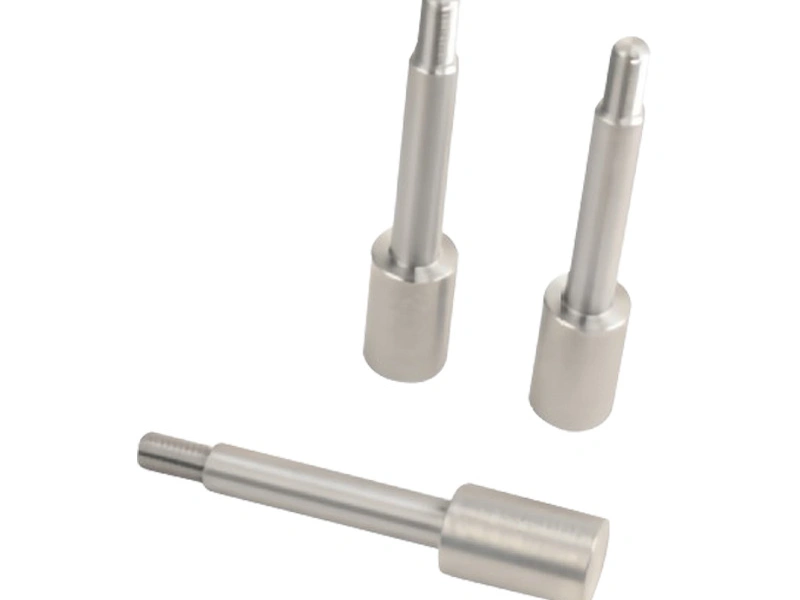
Material Selection: Stainless Steel vs Titanium
Material selection starts with the exact grade and condition, not the family name. Contact, load, wear, corrosion environment, cleaning chemistry, sterilization exposure, heat treatment, stock form, finish, and required evidence determine whether stainless steel or titanium is suitable. Substitution needs design approval because chemistry, strength, machinability, passivation response, and biological-evaluation evidence can change with grade and condition. The procurement specification must also match product form. Bar, plate, wire, forging, and additive feedstock can have different governing requirements even when a familiar alloy designation appears on each certificate. Material acceptance should therefore verify the called-out specification, revision, grade, condition, dimensions, heat or lot identity, and required test results.
Stainless Steel
Stainless steel CNC machining can support instruments, housings, fittings, and device hardware when the selected grade, heat treatment, corrosion environment, and final treatment fit the use. Austenitic 316L is valued where its lower carbon content supports weld-related corrosion control, but 316L does not make every component implant-suitable or automatically clean. Precipitation-hardening grades such as 17-4 PH offer different strength and heat-treatment behavior for appropriate hardware. The specified 17-4 PH condition matters because solution-treated and aged conditions do not provide the same hardness, strength, distortion response, or machining sequence. Work hardening, built-up edge, tool wear, heat tint, embedded iron, and burr formation can affect size, surface, and corrosion performance. Tooling and handling controls should prevent cross-contamination where the drawing or downstream process makes free-iron transfer relevant. The RFQ should state the material standard, grade, condition, hardness where relevant, passivation or electropolishing requirement, and certificate scope. Acceptance should occur after any heat treatment or surface process that can change the controlled characteristic.
Titanium
Titanium CNC machining is selected when a specific grade's strength, density, corrosion behavior, and available device evidence fit the design. Ti-6Al-4V Grade 5 provides high specific strength; Grade 23 ELI has lower specified interstitial limits for applications that require that material definition; commercially pure grades provide different strength and forming behavior. None of these names alone proves biological acceptability. Low thermal conductivity, heat concentration, springback, galling, and reactive chips require controlled tools, cutting conditions, workholding, and coolant management. Thin titanium features can deflect during cutting and recover after tool passage, so a measured in-process size may not represent the free-state result. Surface smearing, embedded debris, overheated material, or damage from aggressive deburring can remain unacceptable even when size passes. Buyers should provide the exact material standard, grade, condition, stock form, alpha-case or surface restrictions where applicable, finish, traceability, and substitution policy. Inspection and cleaning plans must reflect the final surface state and the feature's contact or fatigue significance.
Material Family | Selection Conditions | Manufacturing Risks | Buyer Confirmation |
|---|---|---|---|
Stainless steel | Grade, condition, strength, corrosion exposure, cleaning, and final treatment | Work hardening, burrs, heat tint, embedded iron, and treatment-related size change | Standard, grade, condition, certificate, passivation, finish, and corrosion criterion |
Titanium | Grade-specific strength, contact boundary, environment, surface, and evidence | Heat concentration, tool wear, springback, galling, chips, and surface damage | Standard, grade, condition, stock, traceability, finish, and substitution approval |
Surface Roughness, Finish, and Cleanliness Control
Surface requirements should be assigned by feature and function. Sliding journals, sealing faces, fluid paths, handled edges, coated lands, and cosmetic zones can need different texture, lay, defect, and edge criteria. A final process is justified only when it controls a defined characteristic. Fine cutting, polishing, or CNC grinding may improve an appropriate surface, but each can also change size, form, lay, or edge geometry. Critical dimensions need post-process verification. The drawing and process plan should also distinguish material removal from material addition. Grinding or electropolishing consumes allowance, while coating can reduce clearances and partially close small holes. Masking and post-finish inspection need to follow the functional interface.
Ra is one arithmetic profile-roughness parameter; it does not describe waviness, lay, isolated scratches, torn material, burrs, or residue. A valid surface specification identifies the feature, parameter, filtering or nesting conditions, evaluation length, measurement direction, and final treatment state under the applicable ISO 21920 or drawing framework. Results taken with different filters, directions, stylus access, or post-processing states are not automatically comparable. A generic Ra range copied across the part can over-control cosmetic areas while missing the defect that matters at a seal, pivot, or cleanable passage. Visual criteria should define lighting, magnification, reference standards, and acceptable zones when appearance or isolated defects influence acceptance.
Cleanliness must also be measurable. The requirement should identify targeted chips, coolant, abrasive, polishing compound, ionic residue, free iron, or handling debris; then define sampling or extraction, analysis, limit, lot rule, and packaging state. Washing or ultrasonic energy is a process step, not proof of acceptance. A validation study should establish that the selected chemistry, time, energy, access, rinsing, drying, and handling can remove the target residue without damaging the material or finish. Where a quantitative test is required, blanks, recovery, sample area or part count, analytical method, acceptance limit, and routine frequency need agreement. Supplier machining-clean delivery does not establish device-level cleaning validation or sterility unless those responsibilities and methods are explicitly contracted.
Final-State Risk | Failure Mechanism | Process Control | Acceptance Evidence |
|---|---|---|---|
Fit or seal fails despite passing Ra | Form, lay, scratch, burr, or edge damage is not represented by Ra | Separate size, geometry, texture, visual, and edge requirements | Feature-level results after the last surface-changing operation |
Residue remains in an internal feature | Cleaning lacks access, drainage, extraction, or a defined limit | Match chemistry and energy to material, residue, and geometry | Agreed sampling or extraction, analysis, limit, and lot result |
Finishing changes a critical dimension | Grinding, polishing, coating, or electropolishing alters material or edges | Reserve allowance, protect features, and control final process state | Dimensional and surface inspection after final treatment |
Accepted parts are damaged or mixed | Handling or packaging loses protection, status, or lot identity | Segregate status and package for contact, moisture, and transit risks | Label, quantity, lot, pack condition, and release-record match |
Inspection and Delivery Preparation for Medical Machined Parts
Inspection should match the characteristic rather than defaulting to one instrument. Coordinate measurement can verify accessible datum-related geometry; gauges can confirm fit or thread function; form equipment can assess roundness or straightness; profilometry can measure texture; and magnified visual or borescope checks can inspect edges. The plan should state the final process state, temperature, free or restrained condition, datum simulation, sampling, measurement uncertainty, decision rule, and reaction to nonconformance. Instrument resolution alone is not evidence of reliable acceptance. A method study should confirm access, fixturing, probe or stylus choice, calculation method, repeatability, operator influence, and correlation with the functional requirement. Complex freeform geometry may need an agreed alignment strategy because best-fit alignment can hide a datum-related error. Inspection programming and reporting should use the released drawing revision and identify every reported characteristic unambiguously.
Delivery preparation connects the physical lot to its approved evidence. Released, in-process, and nonconforming parts need controlled status and identity. Depending on the purchase order, release records can include material certificates, special-process certificates, first-article or dimensional results, cleanliness results, deviations, and a certificate of conformity. The record package should state the part number, revision, lot or serial relationship, quantities accepted or rejected, inspection state, and applicable approved deviations. A certificate of conformity should not replace detailed results when the purchase order requires them. Packaging should protect critical surfaces, slender features, open passages, corrosion condition, labels, and lot separation. Protective packaging must not be described as a sterile barrier unless that function is specifically defined and validated. Pack materials and handling controls also need compatibility with the specified cleanliness and downstream processing state.
Typical Tolerance Expectations for Medical Machined Components
There is no universal tolerance for medical machined components. Typical expectations divide requirements into general non-mating dimensions, functional sizes, datum-related geometry, surface and edge characteristics, and post-finish interfaces. A general-tolerance standard such as ISO 2768 applies only when the drawing explicitly invokes the relevant part, class, and scope; it is not a medical tolerance standard. Critical features need individual limits derived from functional stack-up, nominal size, material and heat-treatment state, process sequence, datum framework, final finish, and measurement capability. A positional requirement cannot be replaced by a tighter coordinate size, and a profile requirement cannot be inferred from surface roughness. During RFQ review, the supplier should identify the characteristics that drive special tooling, stable workholding, controlled finishing, or nonstandard inspection. Tightening every dimension increases cost without necessarily reducing device risk.
Consider an engineering scenario involving a thin-wall 316L reusable-instrument housing with a locating bore and sealing face. If both features are measured while clamped before electropolishing, the report can pass even though unclamping releases wall movement and electropolishing changes the bore edge. A sound plan roughs from stable datums, controls residual stock, defines the free-state inspection, reserves finishing allowance, and measures bore size, position, flatness, texture, and edge condition after final treatment. Trial parts should establish the finishing allowance and correlate restrained in-process checks with free-state final results. The reaction plan should address drift before nonconforming parts are mixed with an accepted lot. The buyer then reviews process evidence and assembly risk before approving the tolerance, rather than treating a machine or CMM specification as proof.
Conclusion
CNC medical parts manufacturing is controlled by linked decisions, not by a material name, one tight tolerance, a low Ra value, or a generic cleaning claim. The part becomes manufacturable and auditable when function defines the grade and condition, datum and critical features, final surface and cleanliness state, verification method, traceability, packaging, and responsibility. A supplier should be evaluated on how those controls remain connected from drawing review through final release. The most useful quote makes assumptions and exclusions visible, identifies unresolved acceptance criteria, and separates manufacturing evidence from device-level validation responsibility.
For sourcing, use the medical-device page to frame device requirements, then define whether stainless steel machining, titanium machining, CNC machining, or CNC grinding fits each feature. Before production approval, provide the drawing revision, material specification, final treatments, critical-characteristic list, cleanliness acceptance, inspection and sampling plan, required records, packaging state, and responsibility for device-level cleaning, sterilization, and deviations.
FAQ
What Types of Components Are Included in CNC Medical Parts Manufacturing?
Which Materials Are Most Common in CNC Medical Parts Manufacturing and Why?
Why Are Surface Finish and Cleanliness Critical in CNC Medical Parts Manufacturing?
What Tolerances Are Typically Required for Precision Medical Machined Components?
How Are Medical Machined Parts Cleaned, Inspected, and Prepared for Delivery?