What Tolerances Are Typically Required for Precision Medical Machined Components?
What Tolerances Are Typically Required for Precision Medical Machined Components?
Precision medical machined components have no universal tolerance: noncritical features may suit an early sourcing band near ±0.05 mm, controlled dimensions may approach ±0.01 mm, and selected fits or alignments may require ±0.005 mm or a geometric control. These figures are RFQ screening levels, not medical standards or supplier capability guarantees. The approved drawing must derive each limit from function, stack-up, material state, final processing, datum scheme, and measurement uncertainty. CNC machining should be selected only after those conditions are defined.
Medical tolerance decisions are feature-based. A housing may depend on a datum-related hole pattern, a guide sleeve on bore size and coaxiality, and a shaft on diameter, straightness, and surface state. Applying the tightest number everywhere adds cost without protecting function. The RFQ should separate general dimensions, fits, geometric tolerances, surface requirements, and acceptance rules, then identify which characteristics require first-article and production evidence.
1. Allocate Tolerances from Function and Assembly Stack-Up
Functional features require the tightest control only when variation can change clearance, interference, alignment, sealing, motion, or load transfer. Begin with the assembly's allowable variation and allocate that budget to contributing parts and characteristics. A tolerance copied from a previous medical drawing is not justified unless the function, material, process sequence, and inspection state are equivalent.
The drawing should also distinguish size from geometry. A bore can meet its diameter limit while its axis is misplaced; a face can meet thickness while lacking flatness; a thin wall can measure correctly in a fixture and move after release. The datum reference frame and inspection setup must represent how the component locates in the assembly.
Characteristic to Control | When It Protects Function | RFQ and Validation Action |
|---|---|---|
General linear size | Envelope, clearance, stock, or nonmating geometry | State units, default tolerance, material state, and final process |
Fit bore or diameter | Sliding, location, insertion, sealing, or press fit | Provide mating size, fit intent, temperature, finish, and gauge method |
True position to datums | Hole pattern, alignment, or feature relationship | Name the GD&T standard, datum simulation, modifiers, and inspection setup |
Flatness, form, or profile | Seating, motion, wall geometry, or shaped engagement | Define tolerance zone, restrained state, sampling, and final-state check |
2. Control Hole Location with Datums and a Geometric Tolerance
Hole location often matters more than hole size when a pin, screw, guide, sensor, or mating pattern must align. A true-position tolerance defines a cylindrical zone relative to selected datums, while the hole's size tolerance controls the feature itself. ASME Y14.5 or ISO 1101 can provide the governing geometric language, but the drawing should select one system and revision rather than mixing rules.
Consider a small guide block whose hole aligns an instrument axis. If the hole size passes but the datum setup permits the axis to shift, insertion or targeting can fail even though every coordinate dimension appears acceptable. The buyer should supply the assembly datum logic, material-condition modifiers where justified, mating feature information, and a functional gauge or coordinate-measurement strategy.
3. Derive Fit Tolerances from Mating Parts and Final Conditions
Fit diameters need high precision only when clearance, interference, insertion force, runout, or sealing requires it. ISO 286 fit classes can support linear-size selection, but the nominal size, hole-basis or shaft-basis system, material, operating temperature, coating, and surface state still determine the actual choice. The RFQ must include both mating dimensions and the functional fit, not one isolated diameter.
Where size, roundness, or cylindricity needs refinement after turning or milling, CNC grinding may be appropriate. Grinding capability does not guarantee the finished tolerance. Stock allowance, workholding, thermal control, wheel condition, datum transfer, and post-grind measurement remain part of the process plan. Inspect critical dimensions after every later treatment that can remove material or change the surface.
4. Evaluate Form, Profile, and Thin-Wall Movement after Release
Form and profile controls become critical when compact medical components combine bores, slots, datum faces, shaped tips, or thin walls. Cutting forces and residual stress can hold a wall in position while clamped, then allow it to move after unclamping. A result measured only in the fixture can therefore misrepresent the free-state component that enters assembly.
Process planning should identify the roughing-to-finishing sequence, datum transfers, stress-relief or heat-treatment state, deburring, coating, and final inspection point. Profile tolerances need the correct datum relationship and evaluation area. Flatness is datum-independent, while orientation and location controls require a reference framework. The inspection plan must match the drawing's intended control.
Medical Component Scenario | Functional Controls | Validation Focus |
|---|---|---|
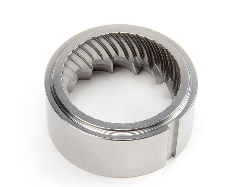
Guide sleeve | Bore size, coaxiality, face orientation, and finish | Datum setup, gauge correlation, temperature, and final state |
Instrument shaft | Diameter, straightness, cylindricity, and surface condition | Form measurement, sampling across length, and process drift |
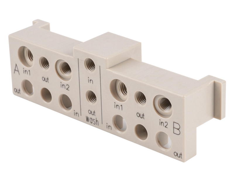
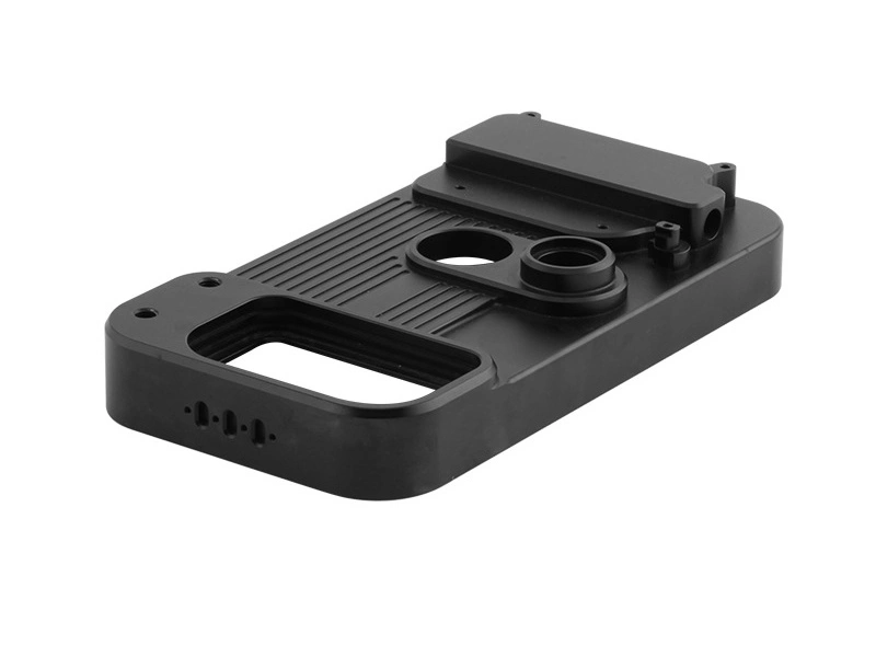
Medical housing | Hole pattern, bore location, face flatness, and profile | Assembly datum simulation, clamp state, and CMM strategy |
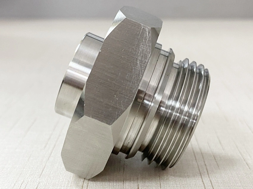
Small connector or fitting | Thread system, sealing face, position, and runout | Functional gauge, seal-test responsibility, and lot evidence |
5. Separate Part Conformance, Process Capability, and Measurement
Repeatability does not replace accuracy; a production lot needs conforming parts, a stable process, and a measurement system capable of resolving the tolerance. One first article can prove that one part met the drawing under one inspection condition. It cannot establish long-term capability. Conversely, a stable process centered outside the specification still produces repeatable nonconformance.
Capability indices such as Cpk are meaningful only with a stable process, sufficient representative data, an appropriate distribution model, and a qualified measurement system. The control plan should connect critical characteristics to sampling, tool-wear response, offset control, material lot, workholding, and reaction limits. Buyers should request raw or summarized evidence appropriate to production risk rather than a capability number without context.
6. Inspect Size and Geometry in the Specified Surface State
Dimensional tolerance and surface condition interact when roughness, burrs, coatings, polishing, passivation, or electropolishing changes the measured boundary or functional contact. A diameter can meet size limits but fail fit because of form error or a damaged edge. A coating can reduce bore clearance, while polishing can round a sealing edge or remove stock from a critical land.
Do not use one Ra target as a substitute for size, form, or cleanability. The drawing should identify the final process state for each measurement, any masking or stock allowance, and whether edges or coated surfaces belong to the acceptance boundary. Where a later finish can change the characteristic, final release data must be collected after that finish.
7. Match the Measurement Method and Decision Rule to the Tolerance
Medical tolerance verification needs a method that can access the feature, resolve the tolerance, reproduce the datum setup, and report the required geometry. A CMM is not automatically best for every bore, thread, thin wall, or surface. The linked pages on quality control in CNC machining, ISO-certified CMM quality assurance, and precision height gauge inspection describe different verification routes; the drawing characteristic should select the route.
Acceptance also needs a decision rule for measurement uncertainty. ISO 14253-1 provides one framework for proving conformity or nonconformity in geometrical product specifications. Buyers should agree on measurement temperature, fixture or free state, datum simulation, equipment, sampling, uncertainty treatment, report format, and dispute method before production. Instrument resolution alone is not proof that a tolerance can be accepted reliably.
8. Build the RFQ around Functional Tolerances and Evidence
A complete medical-component RFQ identifies the drawing standard and revision, units, default tolerances, datum scheme, critical features, mating interfaces, material and heat-treatment state, final finish, inspection condition, sampling, and required records. Early bands such as ±0.05, ±0.01, or ±0.005 mm can screen suppliers, but only the released drawing and acceptance plan define what the component actually requires.
Use CNC machining for features supported by the planned setup, grinding where final size or form justifies a secondary process, and the methods in quality control in CNC machining only when they match the characteristic. Before approving production, confirm the tolerance stack, process stage, measurement uncertainty, first-article evidence, capability plan, and reaction rules for every critical feature.