What Tolerances Matter Most in Medical Device Machining?
What Tolerances Matter Most in Medical Device Machining?
The most important tolerances in medical device machining are datum-based hole position, functional fit, runout or profile, controlled edges, and stability of small features; priority follows device function and risk, not a blanket plus-or-minus value. In medical device machining, buyers should identify datums, mating features, material condition, finishing sequence, and measurement method in the request for quotation (RFQ). Computer numerical control (CNC) machine accuracy and gauge resolution are process inputs, not finished-part acceptance limits.
Repeatability requires evidence across the defined lot, not one attractive sample. American Society of Mechanical Engineers (ASME) Y14.5 provides datum-reference and geometric dimensioning and tolerancing (GD&T) rules; International Organization for Standardization (ISO) 1101 defines geometrical tolerancing symbols and rules. The released drawing controls acceptance. Resources on quality control in CNC machining and coordinate measuring machine (CMM) methods in ISO-certified CMM quality assurance help when their measurement plan matches the part and datum scheme.
1. Hole Position Is Often One of the Most Critical Tolerances in Medical Device Parts
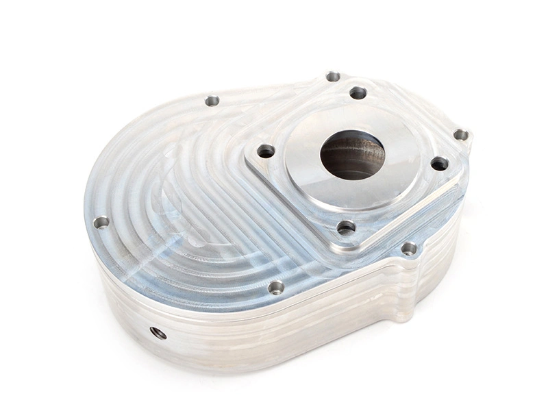
Hole position is critical when a bore locates, guides, pivots, seals, or mounts another feature. A hole can have the correct diameter and still fail if its axis is displaced from the datum reference frame. The resulting error may appear as assembly mismatch, uneven loading, seal damage, or inaccurate instrument motion.
Specify hole size, positional tolerance, datum order, depth, thread or counterbore, and inspection method. A CMM or functional fixture evaluates the relationship; diameter alone cannot prove position. Confirm true position, coaxiality, or profile before quoting.
Critical Tolerance Area | Why It Matters in Medical Devices | Typical Risk If Unstable |
|---|---|---|
Hole position | Relates an axis to functional datums for alignment or guided motion | Assembly mismatch; verify the positional relationship, not diameter alone |
Fit dimensions | Sets clearance, insertion force, sliding play, or interference at a mating interface | Too loose or tight; confirm the mating parts, temperature, and finish state |
Critical edges | Controls burr, edge break, sealing contact, and safe handling at the working feature | Sharp edge or particle release; inspect after deburring and final finishing |
Small feature stability | Protects thin walls, miniature bores, slots, pins, and small datum faces from process drift | Part-to-part variation; link tool life, setup control, and inspection timing |
2. Fit Dimensions Are Critical Because Many Medical Parts Depend on Controlled Assembly Feel and Motion
Fit dimensions cover bore and shaft limits, slots, gaps, threads, and other mating features. Tolerance depends on materials, temperature, finish, coating, lubrication, and clearance or interference; nominal size alone is incomplete.
Measure both limits after the final process and, where possible, use a representative mating part or functional gauge. Deburring, grinding, coating, or cleaning can change an edge or bore. The RFQ should state the mating stack, functional feel, datum, and near-limit decision rule.
3. Critical Edge Condition Matters Because Medical Parts Cannot Tolerate Burr Risk Like Ordinary Industrial Parts
Critical edge condition is a functional requirement because a burr, rollover, sharp corner, or uncontrolled edge break can change fit, cleanliness, handling, and contact stress. Risk is highest at drilled exits, cross-holes, slots, threads, sealing lands, and small instrument tips where a loose chip or sharp edge can affect the device.
Call out the protected edge, allowable break or radius, burr limit, and magnification when required. Deburring must be selective because tools can damage a datum, thread, or seal land. Inspect after deburring and surface processing, and tie the result to part traceability.
4. Small Feature Stability Is Often the Hardest Part of Medical Machining
Tool deflection, wear, heat, clamping force, and datum shift affect small features disproportionately. Thin walls can relax after unclamping; deep bores can drift with chip evacuation; worn tools can change burrs before size leaves the limit.
Use stable datums, supported workholding, tool-life limits, first-piece checks, and staged inspection where features can change. Machine repeatability and caliper resolution are not part-tolerance guarantees. Confirm feature size, wall, setup, material condition, and measurement uncertainty before release.
Medical Part Example | Main Tolerance Focus | Why It Is Important |
|---|---|---|
Guide sleeve | Inner diameter, axis relationship, roundness, and controlled edge | Controls insertion and alignment; verify with a suitable bore or functional method |
Instrument shaft | Diameter, straightness, runout, and final surface texture | Controls motion and handling feel; inspect after grinding or polishing |
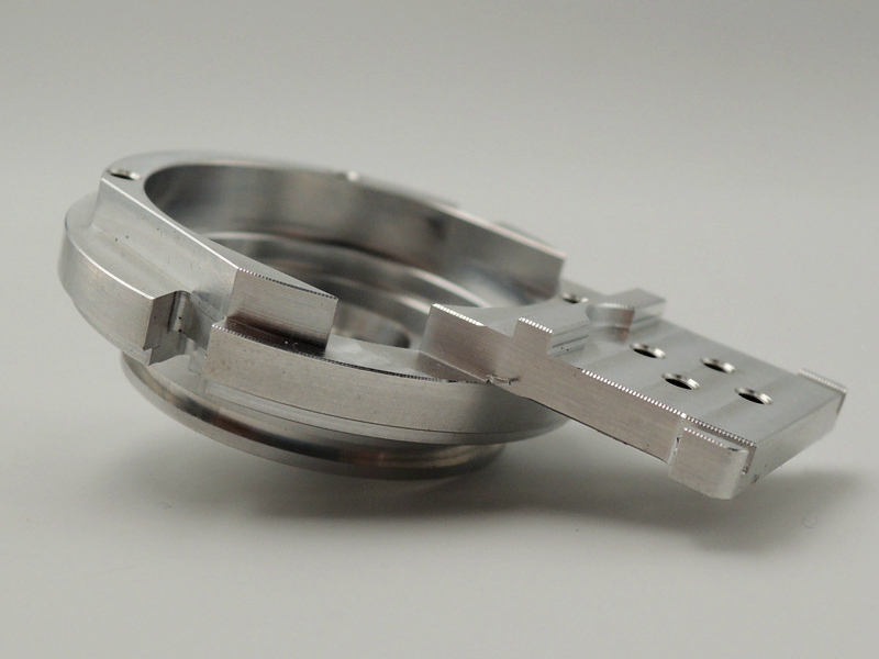
Medical housing | Hole position, face location, profile, and small-feature stability | Controls internal assembly; use the released datum reference frame for measurement |
Connector or fitting | Thread fit, sealing geometry, axis alignment, and edge quality | Controls reliable connection and clean assembly; verify with mating or leak criteria |
5. Repeatability Matters So Much Because Medical Devices Depend on Consistent Part-to-Part Behavior
Repeatability keeps critical relationships within released limits across the lot, setups, operators, and process state. A first article does not prove tool wear, fixture drift, material variation, or post-process change. The control plan needs critical characteristics, sampling basis, reaction, and traceability records.
Compare first-piece, in-process, and final-condition results, not only a final average. Capability statistics support decisions only when distribution, measurement system, and specification fit; they do not replace the drawing or functional test. Request the lot definition and reaction plan in the RFQ.
6. Precision Grinding and Inspection Add Value When the Most Critical Features Need Higher Stability
Standard CNC machining can satisfy many features, while a shaft, bore, or contact surface may need a controlled final operation. CNC grinding can improve size, roundness, runout, and texture when stock allowance, wheel condition, heat control, and datum transfer are planned. It is not automatically better; an unsuitable sequence can burn a surface, remove too much stock, or shift an edge.
Match inspection to tolerance type. A gauge checks a limit or fit; a height gauge establishes a face relationship; a CMM evaluates position or profile when datums and probing are defined. Articles on precision height gauge inspection and CMM quality assurance matter only after uncertainty and the acceptance rule are agreed.
7. The Real Value of Medical Precision Machining Is That It Protects Function, Not Just Dimensions
Functional acceptance links measured features to device behavior. Position may pass while a tolerance stack causes interference; a dimension may pass while a burr, roughness change, or coating blocks assembly. Use a representative mating, motion, seal, or other defined test when the drawing cannot express the risk.
If uncertainty affects the decision, an agreed rule such as ISO 14253-1 can define conformity near a limit; the specification owner must set it. Preserve datum setup, instrument ID, calibration status, final-process state, and nonconformance disposition for traceability.
8. Summary
The tolerances that matter most in medical device machining are the ones that protect a functional relationship: datum-based position, fit, runout or profile, controlled edges, and stable small features. Their limits depend on geometry, material condition, process sequence, measurement method, and the device risk; no universal medical tolerance value replaces the released drawing.
Put the datum frame, critical limits, edge and surface requirements, final-process state, inspection method, and lot or reaction expectations in the RFQ. Reliable machining, selective grinding, and documented quality control connect drawing intent to repeatable medical-device performance.