CNC Lathe Services: Turned-Part Requirements, Tolerances, and Supplier Fit
CNC Lathe Services: Turned-Part Requirements, Tolerances, and Supplier Fit
CNC lathe services should be compared by the turned part's axis, diameter relationships, material state, workholding, inspection evidence, and delivered condition. “Near me” may help with logistics, but location alone does not show whether a supplier can control a slender shaft, a threaded feature, a sealing land, or a concentric relationship. Buyers should define the functional surfaces, stock condition, chucking or collet strategy, measurement state, and change records before choosing a route. A CNC turning route review can organize these questions without making an unsupported capability promise.
Define the Turned-Part Function
Start by identifying what each diameter, bore, shoulder, groove, thread, and face must do. A turned component may locate a bearing, seal a fluid path, carry a fastener, guide a shaft, or provide a clearance interface. State mating hardware, load, motion, pressure, temperature, lubricant, and assembly sequence when they affect acceptance. A nominal diameter without an axis, form, surface, or edge requirement is not a complete manufacturing decision.
Separate size from roundness, cylindricity, concentricity, runout, perpendicularity, thread form, and surface condition. A shaft can measure the right diameter at one point while taper or runout prevents assembly. A thread gauge can pass while the shoulder is mislocated. Write the datum frame, measurement state, and evidence owner for each critical characteristic. If the part is assembled before release, state whether the accepted object is the individual component or the assembly.
Use the Nozzle Views as a Geometry Prompt
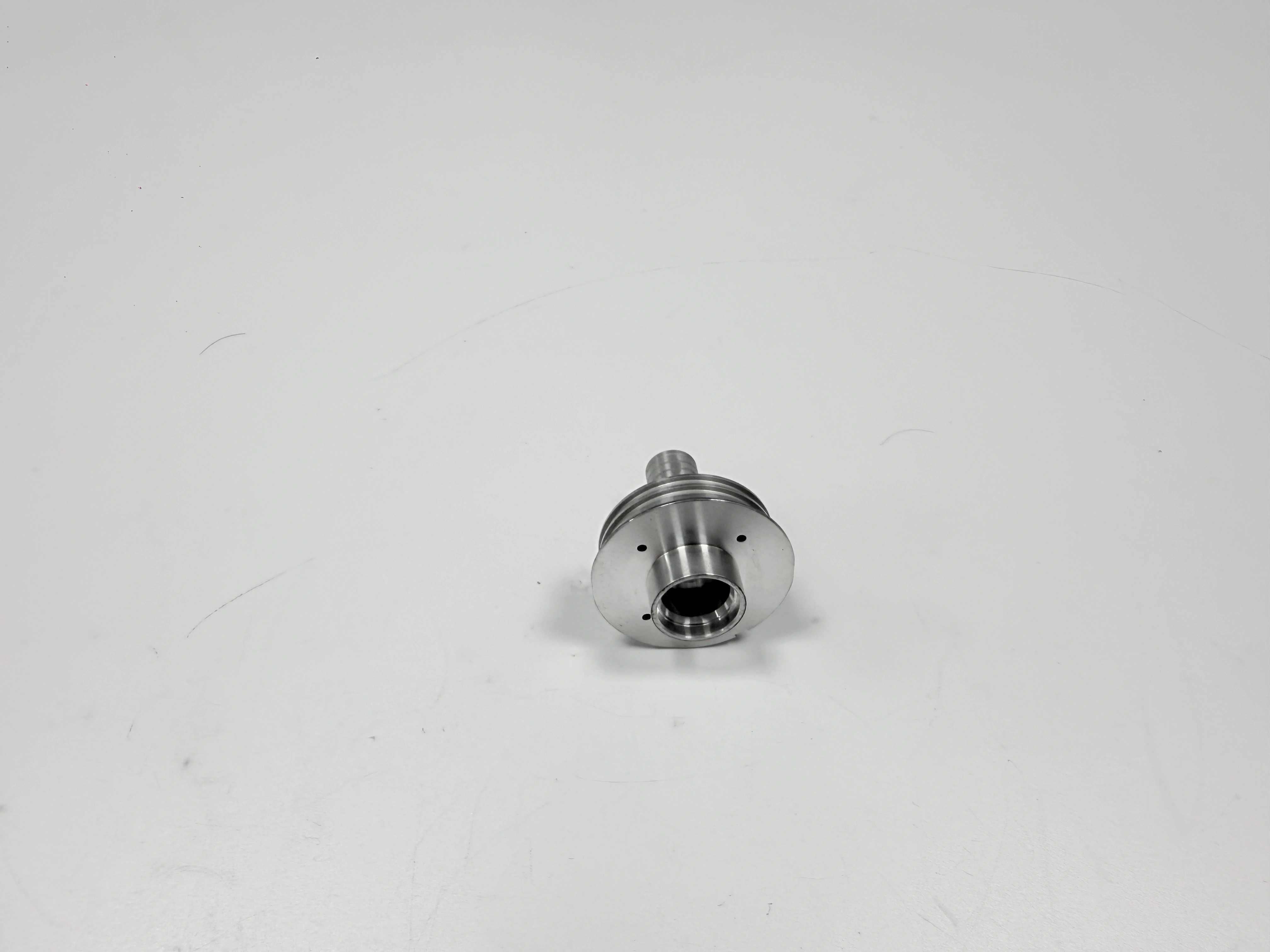
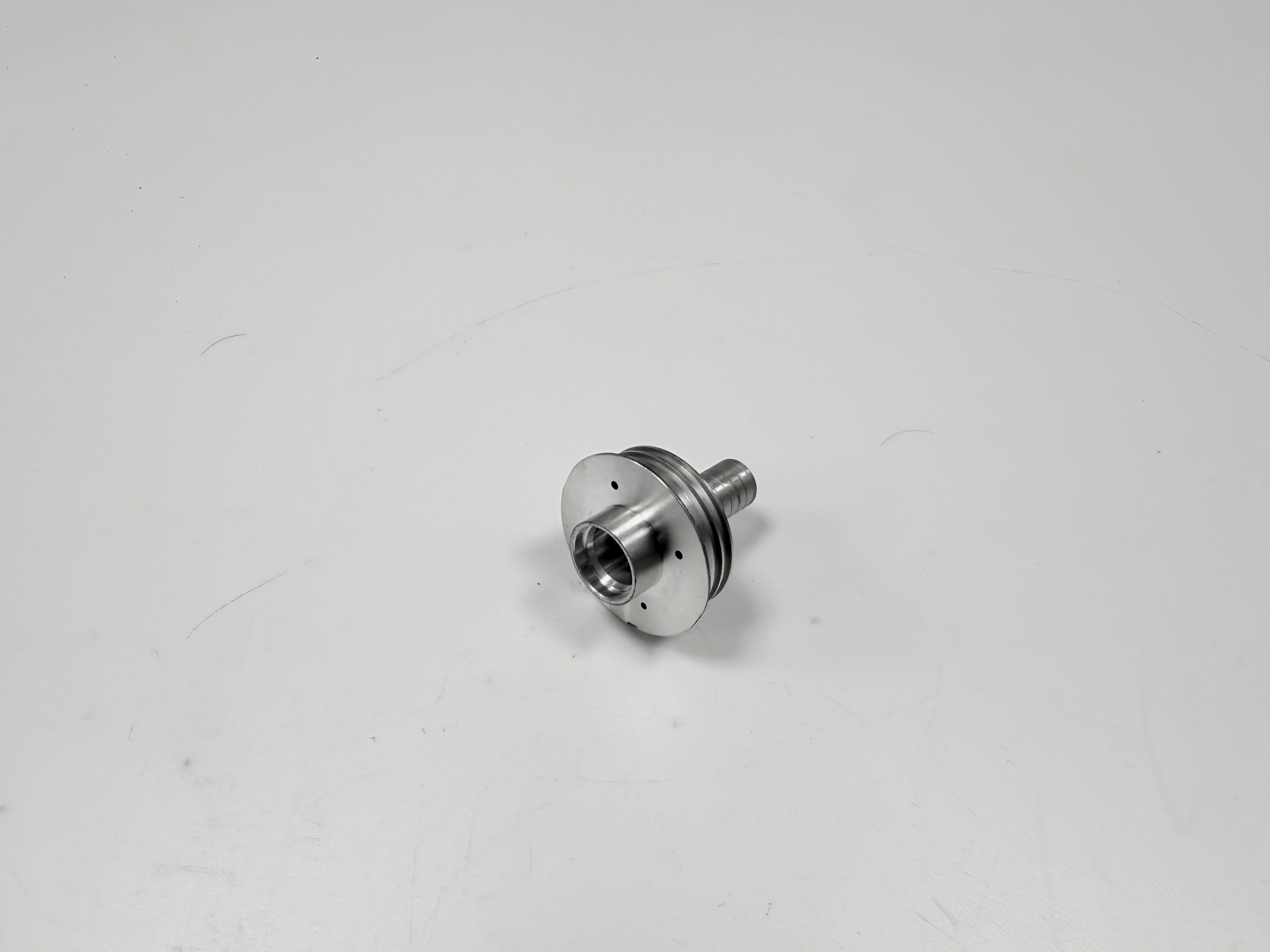
The paired images show one turned cylindrical nozzle-like component with a flange, central bore, stepped diameters, grooves, and small face holes. The views confirm the same physical product and different angles. They do not reveal material grade, pressure rating, thread specification, tolerance, heat treatment, or application. Use the visible geometry to ask about chuck access, bore reach, shoulder control, and cleaning; use the controlled drawing for every engineering claim.
Choose the Turning Route From the Preform
Turning may begin from bar, tube, forging, casting, or a pre-machined blank. The preform controls stock distribution, interrupted cuts, scale, wall thickness, and the axis available to the setup. Record raw size, straightness, material condition, heat or lot, and any prior process. A CNC machining reference can frame route selection, but the actual preform and drawing determine whether a turning-only route is appropriate.
Decide which features are established in one chucking and which require a second setup. A single setup can preserve a common axis, while a second setup may be needed for the flange, face holes, or back-side bore. State the datum transfer and the witness feature used after reclamping. Do not assume that a collet, soft jaw, or three-jaw chuck repeats the functional axis without a verification check.
Control Stock and Runout at Entry
Measure raw or semi-finished stock for diameter, straightness, wall, and runout under a defined support. Record burrs, scale, coating, and damage that could affect seating. Too little stock can leave a casting skin or prior tool mark; too much can increase deflection, heat, and cycle time. Establish lower and upper entry windows for each critical feature rather than one generic allowance.
When heat treatment, stress relief, welding, coating, or aging occurs before final turning, document the state transition and repeat sensitive checks. A material certificate supports identity within scope; it does not prove straightness or distortion. Keep the pre-turn and post-turn results linked to unit identity, revision, fixture, and owner.
Build a Datum Strategy Around the Axis
Name the functional axis, primary face, shoulders, and reference diameters. State contact order, chuck or collet location, jaw engagement, tailstock or steady-rest support, clamp force, and orientation. A convenient outer diameter may be repeatable but unrelated to the assembly axis. If an auxiliary surface is used, document the transformation to the drawing datum and the tolerance consumed.
For a flanged nozzle, distinguish the flange face, bore axis, shoulder, grooves, and face-hole pattern. Decide whether face holes are clocked from a key, a datum flat, or a derived axis. Record how the first setup transfers to the reverse setup. A workholding reference can structure setup questions, but it does not prove the part's axis.
Verify Reclamping and Axis Transfer
Run a transfer check after flipping, replacing jaws, changing a collet, moving a steady rest, or transferring the job to another machine. Use a witness diameter, face, or bore tied to the functional axis. Record setup identifier, contact sequence, runout, temperature, sample identity, and result. A machine coordinate or chuck repeatability claim is not product evidence.
If the transfer check fails, hold the affected units and preserve the original result. Review jaw condition, chip contamination, clamping force, support, stock, and datum interpretation. Re-turning can change the remaining allowance and the relationship between shoulders. Authorize rework only after an owner confirms the stock and all affected CTQs to repeat.
Control Deflection on Slender or Interrupted Parts
Slender shafts, thin walls, deep bores, and interrupted flange cuts amplify tool and workpiece deflection. State length-to-diameter risk, support, tool projection, insert condition, cutting direction, and the process signal used to detect drift. A machine envelope or spindle rating does not prove a finished diameter or runout. Use measured trial cuts and inspect before continuing when stiffness is uncertain.
For a nozzle with a central bore and stepped exterior, map where internal support ends and where the wall becomes flexible. Plan roughing and finishing passes to avoid closing the bore or bending a thin lip. Record coolant and chip evacuation because a trapped chip can shift seating or scratch a sealing surface. A boring reference can frame internal-axis questions, while the turning plan controls the actual process.
Monitor Tool and Workholding Response
Use load trend, chatter, size drift, surface marks, insert wear, runout, and chip form as triggers for a check. A quiet cut does not prove concentricity. A good-looking face does not prove perpendicularity. Link each trigger to a reaction, affected range, and restart approval. When a tool, holder, jaw, support, program, or coolant changes, repeat the characteristics sensitive to the change.
Manage Threads, Grooves, and Shoulder Interfaces
Threads and grooves require functional definitions beyond diameter. State thread standard, size, class, length, lead, runout, relief, crest and root condition, gauge, and mating hardware. For a sealing groove, state width, depth, corner radius, surface, burr, and seal material. For a shoulder, state face runout, perpendicularity, edge break, and contact width. Do not use a generic thread gauge or visual check as proof of every requirement.
Define tool access and inspection access for internal threads, narrow grooves, and deep shoulders. A probe may reach the mouth while missing the bottom. If a feature is inaccessible, state the alternate method and its limitation. Keep thread and groove evidence tied to the same unit, revision, and delivered state.
Protect Bore-to-Face Relationships
When a bore, flange face, groove, and bolt circle work together, measure their relationship in a common datum frame. Diameter at one section does not prove bore axis; face flatness does not prove face runout to the axis; bolt-hole size does not prove clocking. Record sections, angles, depths, temperature, support, instrument, and alignment. A functional assembly check can add evidence but cannot replace unmeasured geometry.
Control Material and Thermal State
Material designation, temper, hardness, casting condition, bar straightness, and heat treatment influence cutting force, tool wear, burrs, and distortion. State the condition before turning and any stabilization or stress relief. Do not infer alloy or hardness from the silver surface shown in the images. If a substitute is proposed, define which conclusions transfer and which require production-state evidence.
Control coolant, cleaning, temperature, and storage when they affect measurement or fit. A warm part can report a different size than a stabilized part; residual chips can alter chuck seating; cleaning can remove residue or expose a scratch. If coating or outside processing follows turning, define before-and-after checks and the delivered condition. A metal finishing reference can frame the state transition, not prove the final dimension.
Write a Reaction for Drift or Heat
Set a reaction for unexpected runout, discoloration, roughness change, thermal growth, chatter, or movement after unclamping. Hold the affected range, identify the process event, and decide whether expanded inspection, rework, replacement, or deviation is authorized. Preserve original and corrected readings. Do not average a warm measurement with a stabilized one or replace a failed result with a later value.
Inspect Turned Parts With Separate Evidence
Use defined methods for diameter, form, runout, location, thread, groove, roughness, and functional fit. A micrometer can measure size at a location; it cannot prove roundness or axis. A CMM report depends on alignment and probe access. A thread gauge demonstrates fit under its own condition. Record units, instrument, calibration, temperature, support, section, and sampling for each characteristic.
For a flanged nozzle, identify bore sections, flange face, shoulder, groove, and face-hole clocking. Include internal and external features and any assembly condition. If a stylus or probe cannot reach a region, document the boundary and alternate evidence. Keep raw traces or coordinate files where the release decision needs more than a displayed number.
Use an Inspection Evidence Table
| Characteristic | Method and state | Boundary |
|---|---|---|
| Diameter | Defined location, gauge, temperature | Not roundness or axis proof |
| Runout or form | Common axis, support, scan or indicator | Not material or fit proof |
| Thread or groove | Specified gauge, profile, depth and mating state | Not all geometry proof |
| Functional fit | Specified hardware, load and environment | Not unmeasured dimensions proof |
The table keeps evidence bounded. A quality inspection reference can organize ownership, while the drawing defines acceptance. If face holes are functional, record clocking, hardware, torque, and assembly state so the result is repeatable.
Control Process and Change Handoffs
Define the sequence from raw stock, first chucking, roughing, boring, threading, grooving, reversing, deburring, washing, inspection, outside processing, and packaging. State when the first piece is approved and which changes trigger expanded checks. A tool or jaw replacement can affect a different CTQ than a measurement-method change. Record the affected unit range and restart owner.
Retain process and inspection records with part, revision, material heat, fixture, tool, program, temperature, and operator or owner. A stable trend under one setup does not guarantee another. If a change cannot be bounded, contain the larger plausible range and investigate before release.
Write an RFQ That Makes Lathe Scope Comparable
Attach controlled drawing and model revisions, material and condition, raw stock, axis and datum scheme, diameters, bores, threads, grooves, shoulders, face holes, runout, roughness, edge, assembly state, inspection methods, sampling, records, outside processing, packaging, and milestones. Ask suppliers to state chucking, collet or soft-jaw assumptions, support, tool reach, chip control, thermal stabilization, and inaccessible regions.
Separate programming, jaws or fixtures, tooling, first-piece, inspection, thread or groove gauging, rework review, outside processing, cleaning, packaging, and freight. Request change notification before material, fixture, tool, program, coolant, measurement, processor, or packaging changes. A quote listing only a diameter and cycle time is not comparable with one that includes axis, runout, and fit evidence.
Screen a Local Supplier on Evidence
Compare whether each candidate explains workholding, axis transfer, slender-part support, thread and groove control, material state, inspection access, outside-process handoff, and change reaction. Proximity can reduce freight or communication time, but it does not prove process stability. A machine list, generic tolerance phrase, or “same-day quote” is not evidence for the pictured geometry.
Ask for an anonymized setup, first-piece, inspection, or reaction format tied to comparable turned features. Prefer responses that state limitations, owners, sample basis, and release criteria. If a supplier cannot explain how a bore, face, groove, and bolt circle are related, keep that gap open before selecting on price or distance.
Release the Turned Part With Explicit Boundaries
Release when revision, material state, stock, workholding, axis transfer, tool and program records, diameter/form/runout results, thread and groove evidence, functional checks, outside-process certificates, packaging, and deviations agree. Hold when a measurement belongs to another state, an internal feature is inaccessible, a reclamp is unverified, or the unit cannot be traced to the setup.
CNC lathe service quality is the fit between functional intent, axis control, workholding, inspection, and records. The nozzle views are geometry prompts, not proof of material, pressure, tolerance, or supplier capability. Let the drawing, actual setup, measured characteristics, and lot-linked evidence determine acceptance. A CNC machining route review can support broader planning while the turning inspection plan controls release.
Neighboring operations should be included only where they change a turning decision. A boring process reference can frame a deep internal axis, while a milling process reference can frame face holes or flats created after the lathe setup. A quality inspection reference can organize datum, gauge, and sampling fields. If a later metal finishing process changes the delivered state, preserve before-and-after evidence. These references support questions; they do not replace the drawing or establish a tolerance guarantee.
For repeat turned work, keep a route baseline that names stock, chucking, support, tool, program, coolant, inspection state, and change triggers. A baseline is valid only within its defined conditions. A different bar heat, jaw set, holder projection, or measurement temperature may require a new first-piece check. Make that boundary visible in purchasing records so “near me” does not become a shortcut around technical equivalence.
Review the failure path before approval: runout after reclamping, a burr under a jaw, tool deflection on a thin wall, a thread that passes while its shoulder is wrong, or a coated part that no longer fits. For each risk, identify the observable trigger, the affected range, the required recheck, and the owner who can release or hold. This turns a location-based search into an evidence-based supplier decision.
Where inspection ownership is shared, a quality inspection handoff should state the same datum, state, and unit identity used at the lathe. Otherwise two accurate measurements may describe different conditions.
FAQ