Which Checks Protect Threads, Grooves, and Shoulder Interfaces?
Which Checks Protect Threads, Grooves, and Shoulder Interfaces?
Threads, grooves, and shoulder interfaces are protected by defining their functional geometry, controlling the turning datum and tool access, and measuring each feature with an appropriate method. A thread gauge, diameter reading, or visual inspection answers only its own question. The buyer should state thread class, groove function, shoulder relationship, surface and burr limits, mating hardware, and delivered state before accepting a turned component.
Define the Thread Function
Specify thread standard, nominal size, pitch or lead, class, handedness, length, relief, runout, crest and root condition, gauge, and mating hardware. State whether the thread carries load, seals, or only retains a cover. A go/no-go gauge demonstrates fit under its defined condition; it does not prove axis, shoulder location, or surface integrity. If the thread is internal, identify depth, tool reach, chip evacuation, and the unmeasured bottom.
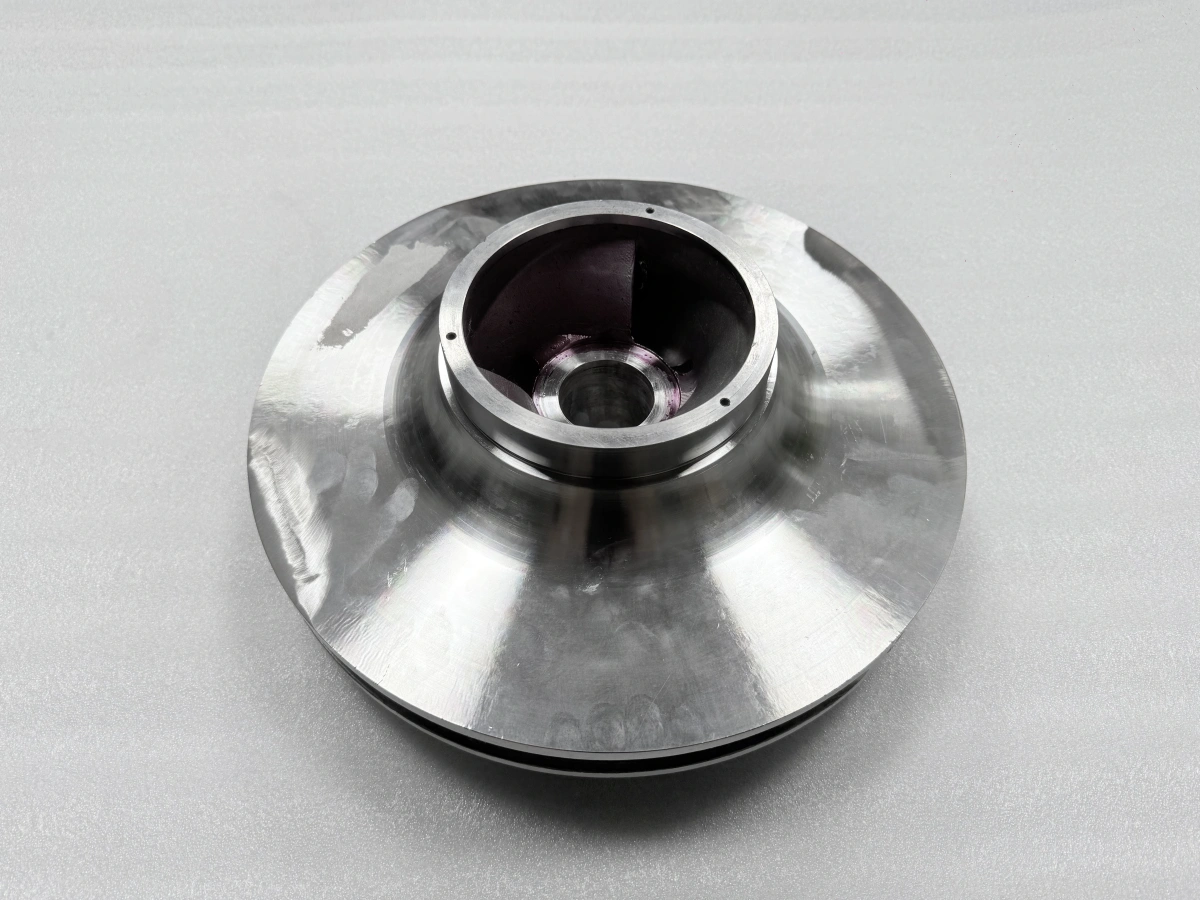
The image pair shows a turned nozzle-like part with a flange, bore, grooves, and stepped cylindrical surfaces. These visible features are geometry prompts only. They do not prove thread specification, material, pressure, tolerance, or application. Use the controlled drawing and approved mating hardware.
Define Groove and Seal Requirements
For a sealing or retaining groove, state width, depth, corner radius, surface, edge break, burr, seal material, compression condition, and inspection. A groove can have correct width while its depth, corner, or axis relationship prevents sealing. Identify whether the groove is measured as-turned, washed, coated, or assembled. Keep surface evidence separate from dimensional evidence.
Control tool access for narrow, deep, or internal grooves. State insert geometry, projection, relief, chip removal, and the reaction to chatter or a damaged corner. A smooth visual finish does not prove that the groove bottom or radius meets the drawing. If a region is inaccessible, define an alternate method and its boundary.
Protect Shoulder Interfaces
State shoulder diameter, face runout to the axis, perpendicularity, contact width, relief, edge break, and mating condition. A shoulder may locate a bearing or seal even when the adjacent diameter is nonfunctional. Measure the face and its relationship to the axis, not only the axial dimension. A functional assembly check can supplement geometry evidence but cannot replace it.
For a flange, identify the datum face and the clocking of face holes or slots. Record chucking, support, and reverse-setup transfer. A convenient outer diameter may not be the functional reference. Keep the axis frame common to bore, shoulder, groove, and hole pattern.
Control Tool and Datum Conditions
Record tool or insert identity, holder, projection, program revision, coolant, pass sequence, and workholding. Define when a tool, jaw, holder, or program change triggers first-piece or expanded inspection. A replacement insert can alter shoulder burrs or groove form even when size remains stable. Preserve the affected unit range and restart approval.
Verify the datum after reversing or reclamping. Use a witness face, diameter, or bore linked to the functional axis. Record contact, runout, temperature, and result. A machine coordinate or chuck repeatability claim is not proof of the finished interface.
Use Separate Inspection Methods
Measure thread fit with the specified gauge and record gauge identity, condition, and result. Measure groove width, depth, and radius with an accessible method and state its calibration. Measure shoulder runout or perpendicularity in the drawing frame. Use a roughness method with location, direction, and cutoff. Each result has a boundary; none should be expanded into a universal pass.
For a deep internal thread or groove, document depth and tool access. If the probe cannot reach the bottom, identify the alternate evidence. Retain raw traces or profiles when a displayed value is insufficient. Record unit, revision, state, temperature, support, and cleaning.
Account for Material and State
Material, temper, hardness, coating, heat treatment, and stress relief affect thread burrs, groove edges, and shoulder movement. State material and condition before turning and after any outside process. A certificate supports identity within scope; it does not prove thread form or sealing behavior.
Define cleaning, lubrication, coating, assembly, and storage. A seal or thread fit can change with residue or coating thickness. Record before-and-after dimensions where the delivered state differs from the machining state.
React to Out-of-Limit Features
Hold the unit when a gauge fails, a groove is damaged, a shoulder shows excessive runout, a burr remains, or a required region is unmeasured. Preserve the original result and process record. Review tool, workholding, datum transfer, material, chip control, and inspection state. Rework requires stock, axis, shoulder, groove, and thread review.
If the affected range is unknown, expand inspection. Do not use a neighboring unit's gauge result to fill a missing record. Release only after the owner approves the evidence and state.
Specify Interfaces in the RFQ
Provide thread and groove standards, mating hardware, seal, shoulder, datum, stock, material, tool access, gauges, profile or roughness method, sampling, records, and change authority. Ask for a redacted report showing gauge identity, shoulder relationship, groove measurements, and reaction history. Require notice before changing tool, jaw, program, material, measurement, cleaning, or coating.
Buyer Action
Approve when thread, groove, shoulder, axis, surface, burr, gauge, and delivered-state requirements are separately defined and evidenced. Hold when a gauge result is presented as complete proof or when a shoulder or groove is unmeasured. Functional interfaces need feature-specific evidence.