Thermoplastic 3D Printing Service | Multi Jet Fusion (MJF)
Introduction: Redefining Low-Volume Production of Plastic Parts
Multi Jet Fusion (MJF) is a thermoplastic 3D printing service for low-volume nylon parts when buyers need functional geometry, shorter iteration time, and lower tooling risk than injection molding. The process is strongest for PA12 and related polymer components with accessible powder removal paths, controlled wall thickness, and tolerances that match additive manufacturing. It is not the right answer for every plastic part. Very tight bearing seats, sealed precision bores, high-temperature exposure, cosmetic Class A surfaces, or millions of identical parts may need CNC machining, molded production, SLA, or a hybrid route. This article focuses on how MJF works, which materials and design conditions matter, and what an RFQ should define before prototype or low-volume production.
Core Principle of MJF Technology: High-Speed, Precision Planar Manufacturing
MJF builds thermoplastic parts by spreading a thin nylon powder layer, jetting fusing and detailing agents, and applying infrared energy across the powder bed. The fusing agent marks the regions that should absorb heat and become solid. The detailing agent helps control edge definition by limiting unwanted thermal spread near boundaries. Accuracy therefore depends on more than printer resolution. Powder condition, layer temperature, material profile, agent placement, wall thickness, orientation, packing density, and cooling all affect the final size and shape. A useful quotation should connect these process variables to the drawing, rather than treating MJF as a single fixed tolerance number.
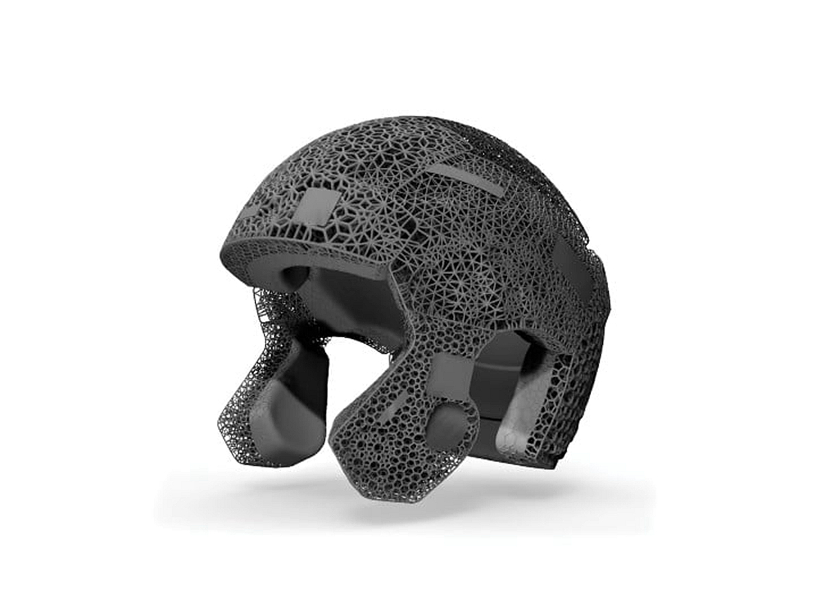
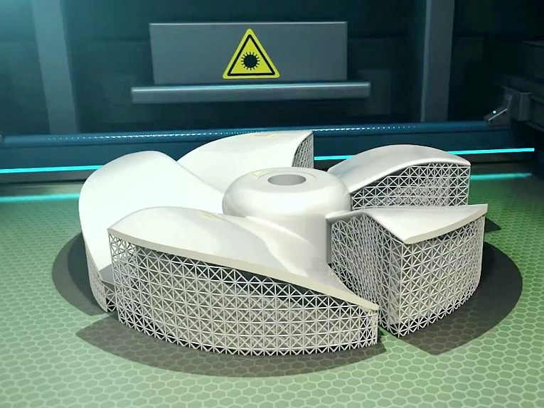
After each layer fuses, the build repeats until the full part is formed inside unfused powder. The powder supports overhangs during printing, so many parts do not need support structures. That freedom helps complex ducts, internal channels, lattices, clips, and nested assemblies, but it also creates inspection and cleaning questions. Deep blind cavities may trap powder. Long flat panels may curl during cooling. Small holes can close at the edge because heat and powder grains interact at the feature boundary. Compared with Selective Laser Sintering (SLS), MJF can offer high throughput because energy is applied across an area instead of tracing each section with a laser. The buyer still needs to confirm depowdering, cooling, finishing, and measurement plans because those steps decide whether the printed geometry becomes a usable production part.
Main MJF Material Options: Exceptional Performance of Nylon Materials
MJF material selection starts with the job the part must perform, not only with the material name. PA12 is the common starting point for housings, clips, covers, brackets, ducts, fixtures, and low-volume functional parts because it balances toughness, dimensional stability, chemical resistance, and printability. PA11 can be considered when impact resistance, ductility, or fatigue behavior matters more than maximum stiffness. The RFQ should state the target material, color, service temperature, chemical exposure, load direction, assembly method, and whether the part must pass a prototype test or a repeated production inspection. A nylon grade that works for a hand-held enclosure may not work for a hot fixture, press-fit insert, thin living hinge, or sealing interface.
For applications requiring higher stiffness and heat resistance, glass bead-filled nylon (PA12 GB) may fit better than unfilled PA12 when the geometry can tolerate lower ductility and a more abrasive filler. Glass beads can reduce shrinkage and raise stiffness, but they can also make thin features less forgiving. Carbon fiber-filled nylon can improve rigidity and dimensional stability for selected structural components, yet the design must still account for anisotropy, edge quality, fastener loading, and post-processing. With these material options, MJF belongs in the wider field of plastic 3D printing, but the best choice comes from comparing geometry, load, heat, finish, quantity, and inspection method. Buyers should avoid approving a material until sample parts or material evidence match the real use condition.
Six Key Reasons to Choose MJF 3D Printing
The main reason to choose MJF is the combination of functional nylon properties, design freedom, and low-volume economics. MJF parts can show more balanced mechanical behavior than filament printing because each layer is fused in a powder bed rather than deposited as a strand. That does not mean every direction, wall, rib, and notch performs identically. Thin walls, sharp inside corners, unsupported tabs, and screw bosses still create local stress risks. The buyer should define whether the part is a visual model, handling prototype, assembly trial part, fixture, or end-use component before judging the process.
Production efficiency is another reason to consider MJF, especially when many small or medium parts can be nested in one build. The planar heating method can shorten print time compared with processes that scan each contour one by one. Total lead time still depends on queue, nesting, cooling, powder removal, blasting, dyeing, inspection, and any machining after printing. A rush project should not look only at printer speed. The practical question is whether the supplier can hold the same material, orientation, and finishing route from the first build to later batches.
MJF also supports complex geometry without printed support structures. This can reduce manual support removal, lower the risk of scars on hidden surfaces, and allow lightweight internal features that would be difficult to machine. The limitation is powder access. Internal channels, enclosed volumes, fine mesh, and deep narrow slots may retain powder after the build. For functional flow passages, a drawing should identify cleaning access, minimum opening size, inspection state, and any air-flow or liquid-flow test. The benefit of design freedom is real only when the unused powder can be removed and the feature can be verified.
For low-volume production, MJF can reduce the tooling threshold that often makes injection molding unattractive for early demand. A quantity range such as 50–5000 parts may be a reasonable screening window, but the actual cost decision depends on part size, packing density, powder refresh policy, finishing, inspection, and scrap risk. Powder reuse should also be treated as a controlled quality variable, not as a simple cost claim. Recovered powder normally needs blending, screening, storage control, and material qualification. If color, elongation, surface consistency, or dimensional trend matters, the buyer should request the powder refresh policy and first-article inspection plan before approving repeat orders.
Post-Processing and Finishing Options for MJF Parts
Post-processing is part of the MJF manufacturing plan, not decoration added after the engineering work is done. Fresh MJF parts normally require cooling, powder removal, media blasting, and final cleaning before inspection. Media blasting gives a consistent matte surface and removes loose powder from accessible areas. Dyeing can create a more uniform black or dark appearance when color consistency is more important than a raw gray surface. These steps can also change edges, small ribs, embossed text, snap-fit feel, and measured dimensions. The drawing should separate cosmetic faces from functional datums, sealing areas, sliding surfaces, and holes that will be measured after finishing.
Surface improvement choices should be tied to the risk the part must control. A smoothing process can reduce rough peaks and improve handling, but aggressive finishing may round corners or soften engraved details. painting can support branding, color matching, and extra surface protection, but coating thickness can reduce small bores, alter snap-fit clearance, or hide surface defects that need inspection. Buyers should specify whether final inspection happens as-printed, after blasting, after dyeing, after painting, or after secondary machining. The same nominal model can measure differently at each state.
MJF vs. Other Plastic 3D Printing Technologies: A Comprehensive Comparison
MJF and SLS both make polymer powder-bed parts, but the best choice depends on material availability, part size, edge detail, throughput, and supplier controls. MJF often fits nested nylon production where PA12 performance, surface consistency, and repeatable low-volume output are more important than a very broad material menu. SLS may still be preferred when a supplier offers a specific polymer, machine volume, or qualification route that MJF does not cover. The buyer should compare actual material data, build volume, powder handling, finish state, and inspection plan instead of choosing only from process labels.
Against FDM, MJF is usually stronger for functional nylon parts with complex surfaces, small bosses, clips, and assemblies that cannot tolerate visible strand lines or weak interlayer bonding. FDM can still be practical for large concept models, simple tooling aids, coarse fixtures, or early ergonomic checks where low cost and size matter more than surface and isotropy. If a part will be screwed, clipped, dropped, flexed, or measured against mating hardware, MJF deserves stronger consideration. If the part only checks package volume or basic hand feel, FDM may be enough.
Compared with SLA, MJF usually provides better toughness for nylon-like functional use, while SLA often wins for very fine visual detail and smooth cosmetic surfaces. Many SLA resins can be brittle, UV-sensitive, heat-sensitive, or less suitable for long-term load. MJF PA12 is better for many clips, housings, and fixtures, but it will not match SLA for transparent parts, high-gloss display models, or extremely fine surface texture. The decision should start from failure mode: impact, creep, heat, chemical exposure, visual quality, tolerance, and assembly load.
Innovative Applications of MJF Technology Across Industries
MJF is useful in automotive and mobility projects when the part is a functional prototype, routing aid, bracket, clip, duct, fixture, or low-volume customization component. The advantage is that design teams can test nylon parts with more realistic strength and thermal behavior than many visual prototypes. The risk is treating a printed part as if it had molded fiber orientation, molded surface, or final production qualification. A good trial part should define load direction, fastener torque, heat exposure, vibration, and inspection points. If the later production route is injection molding, the MJF part should be used to learn geometry and assembly behavior, not to approve every molded-material property.
For medical device manufacturing, MJF can be considered for device housings, assembly fixtures, ergonomic models, test adapters, and selected non-implant polymer components. The buyer must define regulatory class, biocompatibility requirement, cleaning route, sterilization exposure, lot traceability, and documentation before choosing the material. A surgical guide, laboratory fixture, and handheld housing do not share the same risk profile. If the part contacts skin, fluid, medication, or a sterile field, the RFQ should separate prototype evaluation from validated production use. Material certificates, inspection state, and cleaning compatibility should be requested before any regulated release decision.
Consumer products often use MJF for housings, wearable parts, sports accessories, appliance components, and market-validation builds. A useful engineering example is a handheld electronics enclosure with snap-fits, screw bosses, cosmetic outer faces, and internal battery clearance. MJF can build the enclosure quickly for fit testing, but the buyer should mark the snap arm thickness, boss diameter, datum faces, and painted surfaces separately. Snap arms may fatigue if the radius is too sharp. Screw bosses may crack if the pilot hole is undersized. Coating may reduce internal clearance. These are design and validation issues, not only printing issues. A consumer product manufacturing RFQ should include assembly hardware, finish target, drop-test expectation, and mating-part drawings.
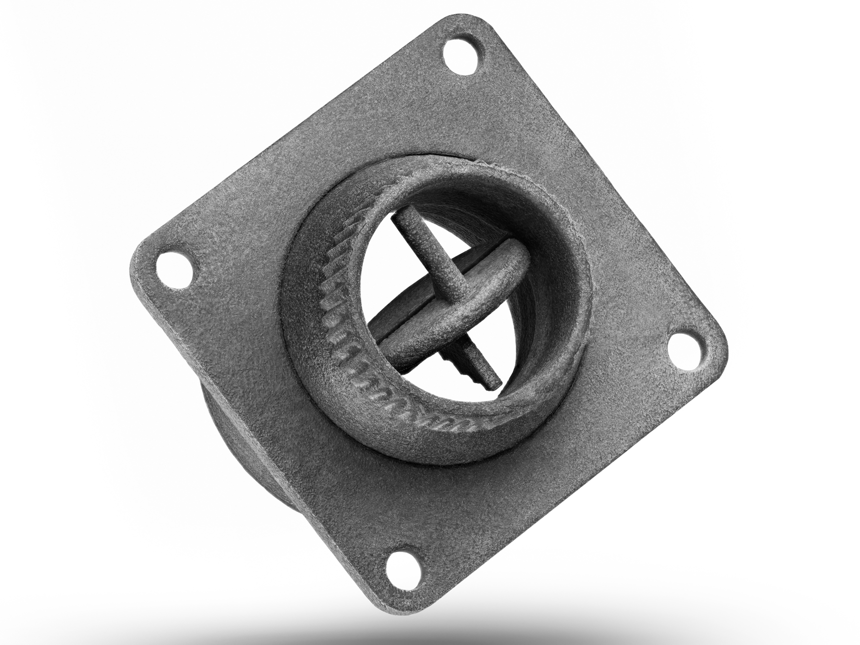
In industrial equipment manufacturing, MJF can support brackets, sensor covers, cable guides, protective housings, custom tools, air ducts, and maintenance fixtures. Industrial parts should be checked against heat, oils, cleaners, abrasion, fastening load, and service environment. A pipe fitting or gear-like feature may look printable, but pressure, wear, sealing, and long-term creep can make another process safer. MJF is strongest when the part needs complex geometry, moderate mechanical performance, and fast iteration. The RFQ should state operating temperature, chemical contact, load case, mating hardware, replacement frequency, and inspection method so the supplier can decide whether printing alone is enough.
Advantages of Neway’s MJF 3D Printing Services
Neway’s MJF 3D printing services should be evaluated by how the manufacturing plan connects material selection, build orientation, powder handling, post-processing, inspection, and any secondary operation. A strong supplier workflow starts with CAD review and RFQ clarification. It then checks wall thickness, powder escape, datum strategy, tolerance class, finish state, and assembly risk before quoting. After printing, the workflow should cover controlled cooling, depowdering, media blasting, dyeing or coating if needed, dimensional inspection, and packaging. If a critical feature needs a bore, thread, flat datum, or tighter surface, the plan should connect printing to machining or drilling instead of pretending the printed part alone controls every requirement.
For rapid prototyping, the service value comes from fast learning: fit, ergonomics, clip behavior, powder removal, surface feel, and early tolerance risk. For low-volume production, the value shifts toward repeatability, batch traceability, fixture logic, finishing consistency, and inspection records. The same CAD file may need different approval criteria in each stage. Buyers should identify which dimensions are informational, which are assembly critical, and which are safety or performance critical. That separation prevents overpaying for unnecessary controls while protecting the features that can stop the part from working.
Design Guidelines: How to Optimize MJF Part Design
MJF part design should begin with wall thickness, powder removal, and tolerance priority. A minimum wall thickness near 0.8 mm can be used as an early screening value for selected geometries, but functional parts often need 1.5–3 mm walls to balance stiffness, print quality, depowdering strength, and handling durability. Thin walls can warp after cooling or break during cleaning. Thick local masses can shrink differently from nearby thin sections. Fillets, ribs, gradual transitions, and balanced sections usually improve stability more than simply increasing every wall.
For holes and channels, a minimum diameter near 1.5 mm is a screening value, not a universal design rule. Deep holes, blind channels, powder traps, and high aspect ratio passages need more clearance or a secondary operation. Snap-fits and living hinges should be designed around PA12 or PA11 fatigue behavior, bend radius, grainy surface, and repeated assembly cycles. Sharp corners concentrate stress, and small tabs can change shape after depowdering. For press-fit inserts, threaded metal inserts, bearing seats, or accurate shaft clearance, the RFQ should define whether the feature will be printed with compensation, drilled, reamed, tapped, heat-set, or machined after printing.
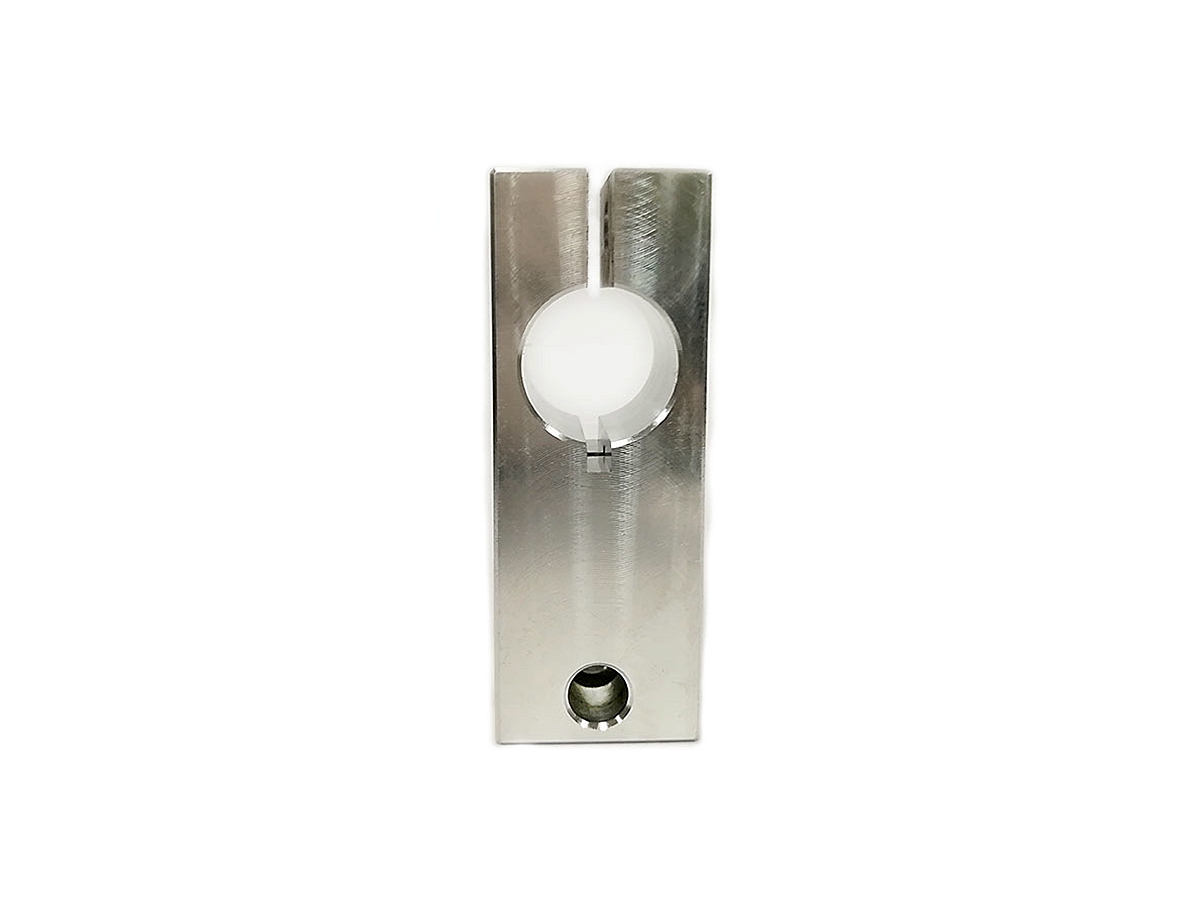
For textures and markings, the design must consider how powder grains and finishing affect edge legibility. A minimum character height near 0.8 mm and depth near 0.3 mm can help raised or recessed details survive printing and cleaning, but font style, orientation, surface angle, and blasting still matter. Cosmetic textures should not share the same acceptance rule as datums or sealing surfaces. For higher-precision features, secondary machining using multi-axis machining services can be used when the MJF blank includes enough stock and the datum scheme supports reliable setup after printing.
Conclusion: Choose MJF for Efficient and Reliable Plastic Part Manufacturing
MJF is a strong choice for thermoplastic low-volume manufacturing when the part needs functional nylon performance, complex unsupported geometry, faster iteration, and lower tooling risk. It is weaker when the project depends on very tight machined tolerances, high-gloss cosmetics, transparent material, high-temperature service, pressure sealing, or very large mass-production cost targets. The buyer’s decision should compare material, geometry, tolerance, finish, inspection, and production quantity before choosing the process.
Before requesting a quote, send the CAD model, drawing, target material, quantity, finish, color, service environment, mating components, critical dimensions, and any prototype test plan. Functional prototypes through nylon 3D printing can answer fit and durability questions quickly. A complementary route beyond traditional CNC machining services can reduce tooling risk when the design suits powder-bed polymer printing. The best RFQ makes the approval state clear: as-printed, finished, machined, inspected sample, or repeat production.
FAQs