As-Machined Finish: Texture, Deburring, and Functional Acceptance
As-Machined Finish: Texture, Deburring, and Functional Acceptance
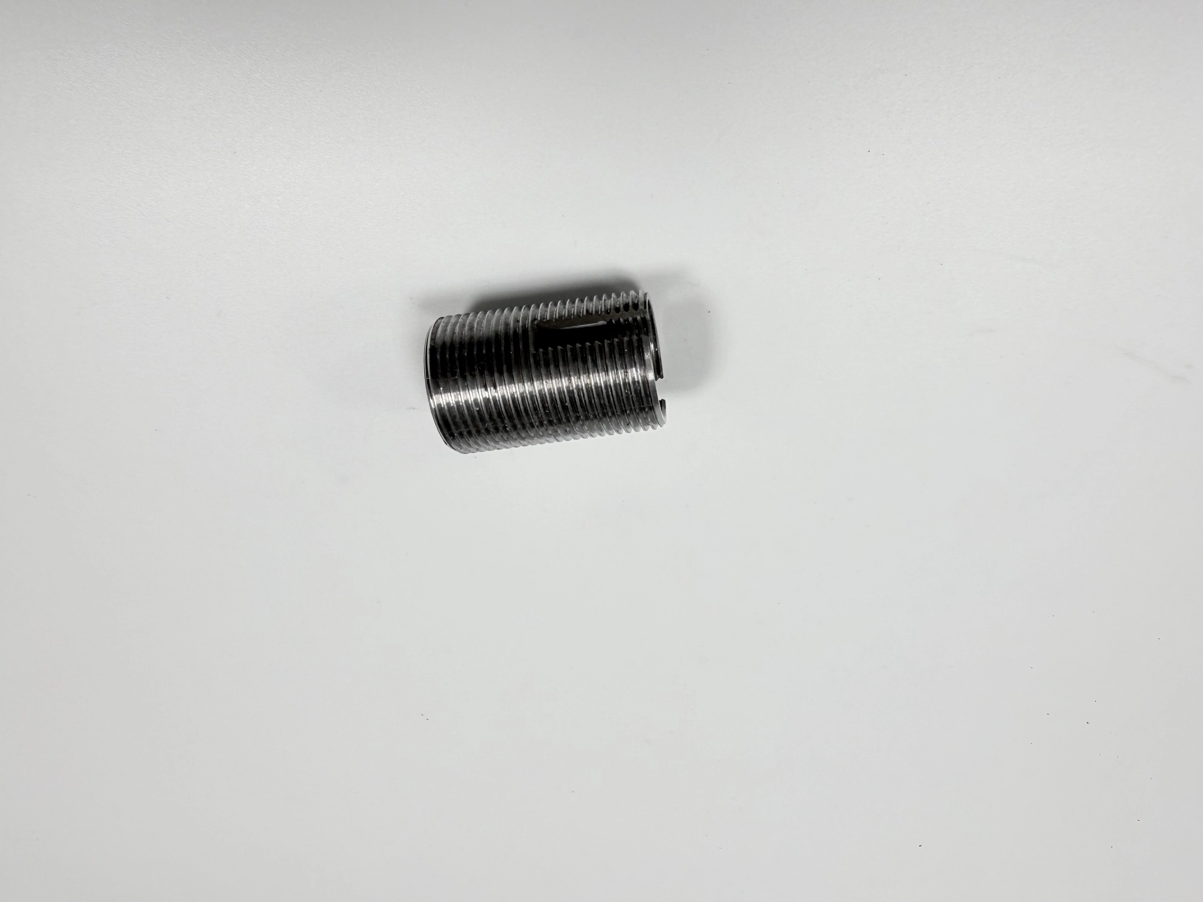
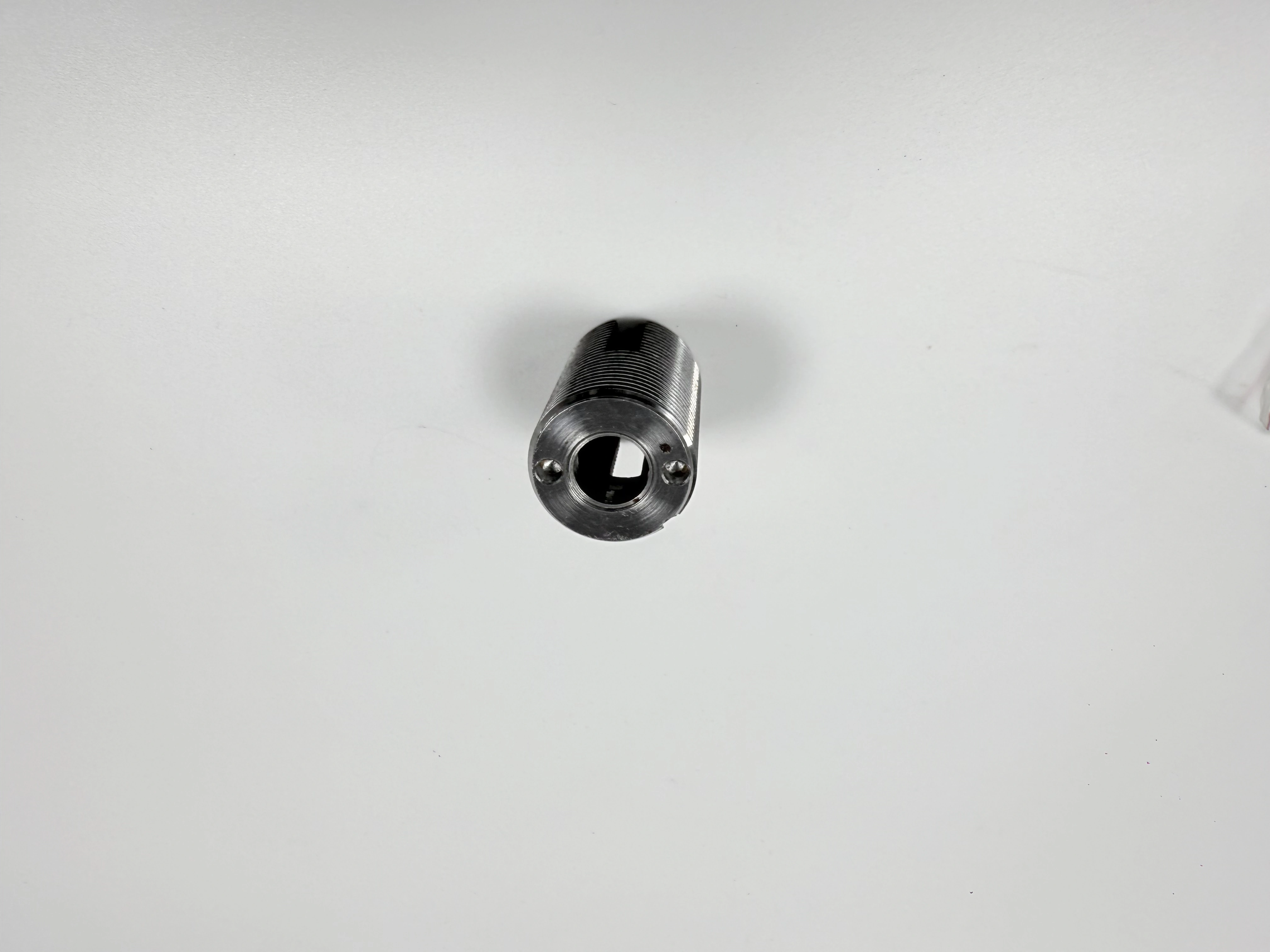
As-machined finish describes the surface state directly after cutting and before a separate coating or decorative treatment; it does not define one universal roughness, burr, or appearance. Buyers should identify functional faces, grooves, openings, edges, material, tool state, cleaning, measurement, and delivered condition before accepting a part. The pictured threaded bushing shows an external thread, end opening, and side opening from two views. Those images support geometry and visible texture only; they cannot prove alloy, thread class, roughness, tolerance, or application. A machined-finish review helps convert appearance into an auditable acceptance plan.
Define the As-Machined State
State the point at which the part is called as machined. It may be after the final cutting pass, after controlled deburring, after washing, or after a protective oil. Each choice changes what the buyer sees and measures. Identify whether the requirement is visual, numeric, dimensional, functional, or a combination. A “standard machine finish” note without state, location, and method leaves the supplier and buyer evaluating different parts. A CNC machining process reference can help organize that state language.
Create a surface and edge register for faces, bores, threads, grooves, shoulders, and rims. Mark sealing, sliding, locating, clamping, cosmetic, and nonfunctional areas. State which surfaces need roughness, flatness, runout, thread fit, burr control, or only appearance. A quality inspection reference can organize fields, but the drawing and acceptance plan remain controlling.
Use the Bushing Views as a Geometry Prompt
The paired images show one cylindrical threaded bushing with an external thread, an end opening, and a side access feature from different angles. They confirm the same physical product and a changed view. They do not reveal material, thread class, pitch, roughness, tolerance, pressure, load, or application. Use the views to ask about thread protection, burr removal, access, and measurement; use controlled documents for engineering conclusions.
Separate Function From Appearance
A thread may need fit and crest protection, a bore may need size and surface, and an end face may locate a mating component. A visible spiral mark may be acceptable on a nonfunctional exterior but unacceptable on a sealing land. State the mating condition, lubricant, temperature, preload, and assembly sequence when they alter acceptance. Do not substitute a polished appearance for a defined functional check. For milled support faces or slots, a CNC milling reference can frame access questions without setting a finish limit.
For a threaded bushing, distinguish major diameter, minor diameter, pitch diameter, lead, runout, shoulder location, opening, side port, and edge break. A thread gauge can show engagement under its own condition but cannot prove all geometric relationships. A turning reference can frame thread and face operations; it cannot establish the required class without a controlled specification.
Write the acceptance sequence in the same order that the bushing is used. Confirm opening cleanliness before inserting a mating part, check thread engagement before applying torque, and evaluate the shoulder or end face after the component is seated. If a check is performed only after an aggressive cleaning or hand deburring, record that state because it may not represent the delivered condition. The sequence helps separate a dimensional defect from a handling or assembly effect.
Keep cosmetic expectations narrow. A consistent turning mark on an outside diameter may be acceptable while a raised burr at the side opening is not. A darkened or oiled surface may change appearance without changing function, but it can also hide a chip. State which visual features trigger containment and which are informational. This prevents operators from polishing a part to meet an unstated appearance preference.
Protect Threads During Finishing
Deburring, brushing, washing, coating, and packing can damage or contaminate a thread. Define permitted burr, crest condition, lead-in, masking, cleaning, and protective packaging. State whether a thread is inspected before or after coating and whether a plug, ring, or mating component is used. If a thread is reworked, preserve the original result and identify the unit.
Tool wear, chip evacuation, insert geometry, coolant, and stock condition affect thread form and surface. Record tool, program, setup, and trigger for change. A fresh tool result does not automatically represent later units made after wear. A threading reference can describe measurement options, but the acceptance class and method remain part-specific.
Measure Texture With Direction and Context
When roughness matters, state parameter, direction, cutoff, filter, evaluation length, instrument, sample, and state. A reading on an outside diameter may not represent an end face, bore, or thread flank. A stylus may not reach a root; an optical method may be sensitive to reflection or oil. Record accessible regions and boundaries rather than implying full surface coverage.
Preserve raw traces or values when near a limit. Record instrument identity, resolution, calibration, operator, temperature, support, cleaning, and timing. Do not round a borderline value into a pass. Roughness evidence does not prove flatness, runout, hardness, material, or thread fit.
Plan access before selecting the instrument. The end face may accept a straight traverse, while an external thread or side opening requires a different fixture or optical view. A stylus that bridges a crest and root can understate a local defect. Record the measured segment and avoid extrapolating it to the entire thread. If the requirement is a functional fit, pair the trace with a defined mating or gauge check.
Use repeat readings to detect method variation, not to average away a bad value. If two readings disagree, review direction, support, cleaning, temperature, and operator placement. Preserve both results and the investigation. A small lot can reveal a process shift, but it cannot prove a long-term capability index without a defined state and sufficient sample.
Use Visual References Carefully
A visual comparator can support cosmetic acceptance when its material, process state, lighting, viewing distance, and permitted marks are controlled. It cannot prove a hidden thread root or numeric roughness. Record the reference revision and inspector. If operators disagree, define a measured method or approved sample instead of averaging opinions.
When the buyer changes the reference sample, preserve the former sample identifier and note the effective date. A new sample can change appearance acceptance even when the cutting process is unchanged. Treat it as a controlled acceptance revision and decide whether existing units need reinspection.
Control Burrs and Edge Breaks
Define edge break, radius, burr direction, nick, scratch, and sharp-edge limits for functional and cosmetic surfaces. A side opening may need a controlled lead-in, while an end face may need minimal removal to preserve location. Manual deburring can enlarge an opening or damage a thread. State method, accessible edges, inspection, and reaction.
Inspect before and after washing, coating, oiling, and assembly when they change the delivered condition. A visual check can identify a burr but cannot prove a radius or thread class. Record original and reworked observations. A deburring reference can frame methods without establishing the acceptance limit.
Protect a thread lead-in and the edge around the side opening from over-deburring. A file or abrasive can remove a burr and also alter a chamfer, reduce wall thickness, or change a flow path. Define the maximum permitted removal and the inspection that detects it. If a burr is removed manually, identify the operator, method, unit, and reinspection. A replacement part should retain the original failure record.
Check Recesses and Side Openings
Recesses and side openings can retain chips, resist a probe, or receive uneven deburring. State depth, edge, thread, cleanliness, and inspection access. If the side opening connects to a passage or pressure boundary, define the functional test and evidence separately from visual finish. The image shows an opening but cannot prove a passage, seal, or pressure rating.
Keep Material and Tool State Traceable
Material designation, temper, hardness, stock condition, residual stress, and temperature affect texture, burrs, tool wear, and dimensions. Record certificate and heat or lot identity. Do not infer alloy or hardness from the silver appearance in the images. If a substitute is proposed, identify which finish and geometry conclusions transfer and which need a new trial.
Record tool, insert, program, coolant, support, fixture, and operation for the accepted state. A setup reversal or tool replacement creates a new state that may require a first-piece check. Keep the measurement and material records linked to units or sub-lots.
Material and tool records should also identify the stock entry and the surface state at each operation. If the bushing is cut from a remnant or a different temper, the same toolpath may produce a different burr or thread finish. A material-selection reference can frame the questions; the certificate, heat identity, and measured result remain the evidence.
Control Temperature and Cleaning
Measure after the defined stabilization and cleaning condition. A warm bushing, oil film, chip, or wash residue can change thread engagement, roughness, or opening size. State room and part temperature, drying, support, lubricant, and timing. If a coating follows machining, define before-and-after checks and delivered-state acceptance.
Build a Characteristic-Specific Plan
Inspect thread fit, opening size, end-face location, side opening, runout, surface, burr, and cleanliness separately when they drive function. State datum, instrument, method, sample, unit, support, temperature, and reaction. A thread gauge does not prove runout; a roughness trace does not prove thread form; a visual check does not prove material.
Include an explicit handoff review before packing. Reconcile thread and opening results with the active revision, material lot, setup, and delivered-state requirements. If a certificate, measurement, or label disagrees, hold the unit and identify the owner. A short reconciliation prevents a finished-looking bushing from being released with an incomplete evidence chain. A CMM inspection reference may help with location evidence when the feature is accessible to that method.
Every-unit checks may be justified for a small lot when a single bushing failure blocks assembly. Sampling may suit lower-risk exterior texture after a stable state is shown. A tool, fixture, material, cleaning, or outside-process change creates a new population. Link each result to identity and state.
Use a characteristic register that maps thread, opening, face, side feature, edge, and surface to method, datum, state, sample, and owner. The register can show that a plug gauge covers engagement while a CMM or optical method covers location and profile. It can also expose a missing check before the shipment is packed. Keep the register with the inspection report and change record.
Make Uncertainty and Access Visible
Review alignment, instrument suitability, calibration, support, temperature, and repeatability near a limit. If a thread root or side opening is inaccessible, state the alternate method and boundary. A functional assembly check adds evidence but does not replace an unmeasured requirement. Preserve raw readings and failed values.
Sequence Machining to Protect Finish
Plan roughing, threading, boring, facing, deburring, washing, and inspection so critical surfaces remain supported and accessible. Leave controlled stock for a final relationship when needed. After a reversal, recheck the transfer feature. Record operation, datum, tool access, support, and inspection point in the process map.
Outside coating, passivation, or assembly can alter a thread, opening, edge, or surface. Record processor, specification, batch, masking, before-and-after dimensions, and delivered condition. A finishing reference can frame process changes but cannot certify this bushing's final state. If the order is part of a broader release, CNC production planning can help keep the state transition visible.
Plan a clean handoff between cutting and finishing. Remove chips without damaging the thread, keep units segregated, and identify the condition in which the first piece is approved. If an outside processor changes a dimension or surface, repeat the affected check before release. A certificate supports the processor's stated work within scope; it does not replace a delivered-state measurement.
Hold the First Piece
Approve a first piece against the frozen revision before releasing the lot. Confirm thread fit, opening, side feature, face relationship, burr, surface, and post-process condition. Record material, tool, setup, instrument, and owner. A first-piece pass does not release later units after an undocumented change.
Make Finish Scope Comparable in the RFQ
Provide drawing and model revisions, functional surfaces, thread and opening requirements, roughness or visual reference, edge and burr criteria, material, tool or process boundary, inspection, sample, outside processing, cleaning, packaging, records, and change authority. Ask suppliers to separate finishing, deburring, gauges, inspection, coating, cleaning, packaging, freight, and engineering changes.
State quantity breaks and assumptions. A higher quantity may use a dedicated tool, fixture, reduced sample, or different cleaning route. A unit discount is not proof that the same finish is stable. Request a redacted first-piece and reaction format.
Ask suppliers to separate the cost of thread gauges, roughness readings, manual deburring, cleaning, protective oil, coating, packaging, and reinspection. If the bushing requires a special fixture to protect the thread or side opening, show that line and its reuse condition. A transparent quote lets the buyer choose a finish state without silently removing evidence.
Screen for Surface Evidence
Compare suppliers on tool state, thread protection, deburring method, measurement direction, instrument, material trace, cleaning, outside-process handoff, packaging, and reaction rules. A machine list or “as-machined included” phrase is not enough. Prefer a response that states limits, owners, sample basis, and evidence retained.
Ask for a redacted first-piece format showing the surface location, method, state, result, and disposition. This reveals whether the supplier can preserve evidence without requiring proprietary process details.
Release the As-Machined State With Boundaries
Release when each functional surface and edge has a requirement, method, state, sample, owner, and reaction, and when material, tool, setup, inspection, outside processing, cleaning, and packaging agree. Hold when “as machined” is undefined, a thread is judged only visually, a groove is inaccessible, or a rework pass erased the original result.
As-machined finish is a useful description only when it is tied to the surface, process state, and evidence that the buyer will accept. The paired bushing images show threads, openings, and visible texture from two views only. Let the drawing, material record, tool and setup history, measurements, functional check, and receiving condition determine whether to accept, revise, or add a finishing operation.
Keep the release statement tied to the inspected surfaces, state, sample, and method so a later order can be compared without expanding the original claim. At shipment, protective parts packaging guidance can be used to record how threads and openings were protected, while the acceptance decision remains tied to the inspection record.
Record the acceptance moment as carefully as the acceptance value. A bushing approved before washing, after oiling, or after an outside process belongs to a different evidence state. Note the revision, unit identity, temperature, support, and operator at release, then preserve any later reinspection as a separate event. This small timing record keeps a visible finish decision tied to the condition the buyer actually receives.
That boundary keeps “as machined” useful for both engineering and purchasing decisions.
FAQ