Aerospace Machining Solutions: Precision Requirements for Flight-Critical Components
Aerospace machining solutions combine design-authority criticality, material-specific process planning, datum-based feature control, traceability, inspection, and release evidence for parts used in the aerospace and aviation industry. Flight-critical status cannot be inferred from a part name or shape. Buyers should provide the released drawing, criticality or quality clauses, material condition, functional features, special processes, inspection scope, and required records before a supplier defines the manufacturing route.
The solution must match the individual part. A thin bracket, multi-face housing, threaded connector, and heat-exposed sleeve have different failure modes even when all are machined accurately. Material condition, roughing sequence, fixture restraint, datum transfer, tool wear, unclamping, heat treatment, coating, and final inspection state can alter conformity. A credible proposal therefore connects each drawing requirement to a process step, control method, acceptance record, and approved response when the result departs from plan.
Flight-Critical vs Structural Aerospace Parts
The design responsibility holder and released program data define whether a component is flight-critical, structural, or subject to another controlled classification. A supplier cannot assign or downgrade criticality from appearance. The classification determines which failure consequences, approvals, special processes, inspection points, traceability, change controls, and release evidence are flowed into the purchase order and manufacturing plan.
Structural does not mean noncritical or loosely controlled. A bracket can redirect load through a fastener pattern; a housing datum can position another system; a mounting face can distort an assembly. The practical distinction is not “tight” versus “ordinary” machining. It is which functions and failure consequences the design authority has identified, how the drawing controls them, and what objective evidence the contract requires before release.
Part Classification | Who Defines It | Buyer Data Needed | Manufacturing Decision |
|---|---|---|---|
Flight-critical or controlled critical feature | Design authority and released program requirements | Criticality, drawing revision, feature notes, approvals, and release evidence | Map each controlled feature to process, validation, records, and change authority |
Structural or assembly-support component | Released design and contractual quality requirements | Load interfaces, datum scheme, fit, weight, material, and inspection scope | Control geometry and documentation according to function, not a lower assumed standard |
Typical Aerospace Machined Components
Aerospace machining can support brackets, housings, connectors, sleeves, fittings, mounts, and other released component types, but the part family does not define the process by itself. Buyers and suppliers must identify the functional interfaces, material and stock condition, accessible setups, distortion risks, edge and surface requirements, special processes, and final verification state. The following examples show how the decision changes by geometry.
Brackets
A bracket often combines a fastener pattern, mounting faces, pockets, thin ribs, and weight-reduction features. The main risk may be movement after roughing or unclamping rather than cutting accuracy at the machine. Consider a thin-wall Ti-6Al-4V bracket with position-controlled holes. A sound route leaves stable stock for datum re-establishment, separates roughing from finishing when necessary, and verifies the hole pattern in the released inspection state. The buyer should define material condition, datum references, free-state or restrained measurement, edge requirements, and any post-process inspection.
Housings
Housings can combine bores, sealing faces, mounting patterns, internal pockets, threaded ports, and multi-axis relationships. Their failure mode is often a datum-transfer or sequence problem: each feature may meet size, yet the assembled interfaces do not share the required relationship. The process plan should show which setup establishes the primary datum, how later setups recover it, when stress or coating may move a surface, and how bores, ports, profiles, and sealing zones will be evaluated together.
Connectors
A connector may depend on thread form, pitch diameter, lead-in geometry, shoulder location, runout, sealing surface, and surface damage limits. A go/no-go thread result cannot prove every relationship or surface requirement. The drawing and contract should identify the thread standard, gauge class, datum relationship, torque or functional tests owned by each party, coating allowance, and inspection record. Burrs at cross-holes or damaged lead threads can defeat assembly even when an isolated diameter is conforming.
Engine-Adjacent Parts
Engine-adjacent describes location, not a universal material or acceptance category. Temperature, vibration, fluid exposure, load, life requirement, and system consequence must come from released engineering data. A fitting, sleeve, housing, or connector in this area may need a heat-resistant alloy, controlled surface integrity, special cleaning, or a qualified outside process. The supplier should not infer these requirements. Buyers should flow down the exact material specification, condition, special-process approval, prohibited damage, and final verification scope.
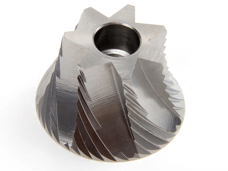
Typical Part | Functional Focus | Likely Failure Mode | Validation and Buyer Action |
|---|---|---|---|
Bracket | Fastener pattern, mounting faces, thin ribs, and weight | Datum shift or wall movement after roughing and unclamping | Define restraint state and verify pattern-to-datum relationship after final release |
Housing | Bores, ports, sealing faces, and multi-face interfaces | Setup transfer creates acceptable local sizes but incorrect feature relationships | Review datum transfer and inspect interacting features in the final process state |
Connector | Thread, shoulder, lead-in, runout, and sealing geometry | Burr, coating buildup, or axis error prevents engagement or sealing | Specify gauge, geometric, visual, and post-coating checks needed for acceptance |
Engine-adjacent component | Material condition, surface integrity, environment, and controlled interfaces | Unapproved material/process assumption or surface damage reduces suitability | Flow down service-driven specifications and approved process/record requirements |
Common Materials in Aerospace Machining
Aerospace machining commonly involves titanium alloys, nickel-based superalloys, and high-strength aluminum alloys, but a family name is not a manufacturing specification. Exact grade, condition, product form, heat treatment, service environment, geometry, and final process state control the selection. The design authority chooses the material; the machining supplier identifies manufacturability, inspection, lead-time, and substitution risks without changing the callout unilaterally.
Titanium
Titanium CNC machining must account for the specified alloy and condition. For alloys such as Ti-6Al-4V, low thermal conductivity can concentrate heat near the cutting edge, while elastic recovery, tool wear, and thin-wall compliance can change size or burr formation. A stable route manages tool engagement, heat, stock distribution, fixture load, and inspection after unclamping. The buyer should provide the material specification, condition, stock form, critical surfaces, edge limits, and any approved thermal or surface process.
Superalloy
Superalloy CNC machining often addresses nickel-based grades selected for strength or environmental resistance at elevated temperature. High cutting forces, retained strength, work hardening, heat at the cutting zone, and notch wear can destabilize dimensions and surface integrity. The process should control tool condition and avoid rubbing or repeated passes that harden the surface. Buyers should identify the exact grade, condition, surface-damage restrictions, post-machining processes, and evidence needed after those processes.
Aluminum
Aerospace aluminum can support brackets, housings, and structural interfaces when the released design selects a suitable grade and temper. Machinability does not eliminate risk. Plate residual stress, asymmetric stock removal, thin walls, burrs, fixture pressure, anodizing, or conversion coating can move geometry or reduce hole size. The manufacturing plan should connect roughing balance, datum recovery, edge control, cleaning, coating allowance, and post-process verification to the specified material and part shape.
Material Family | Selection Condition | Machining Risk | RFQ and Validation Decision |
|---|---|---|---|
Titanium alloy | Released grade/condition and service-driven strength, mass, or corrosion need | Cutting heat, recovery, tool wear, burrs, and thin-wall movement | State stock form, critical surfaces, edge limits, and final inspection condition |
Nickel-based superalloy | Released grade/condition for temperature, load, or environmental requirement | Cutting force, work hardening, notch wear, heat, and surface damage | Define damage limits, special processes, tool-control evidence, and release checks |
High-strength aluminum alloy | Released grade/temper for weight, structure, interface, and environmental needs | Residual-stress distortion, thin walls, burrs, and coating dimensional change | Define temper, stock, coating, datum recovery, and post-process acceptance state |
Why Traceability and Documentation Matter in Aerospace Machining
Traceability and documentation create a reviewable chain from released requirements to shipped parts. The required package may connect part number and revision, material certificate and lot, program or work order, inspection status, nonconformance and deviation disposition, approved outside processes, final report, and release authority. The exact records depend on the contract and customer quality clauses; a generic certificate bundle does not prove the chain is complete.
The supplier workflow should preserve those links through material receipt, job release, roughing, datum re-establishment, finishing, deburring, cleaning, heat or surface treatment, inspection, packaging, and shipment. If a bore trend or coating problem appears, the records should identify affected parts and the process stage for investigation. Buyers should state lot or serial rules, record format, retention, special-process approvals, and shipment documents in the RFQ rather than negotiate them after production.
Evidence Area | What It Must Connect | Buyer Confirmation Before Release |
|---|---|---|
Material traceability | Specified grade, condition, heat or lot, stock issue, and delivered part identity | Match the certificate and lot reference to the drawing callout and shipment |
Inspection records | Controlled characteristic, method, datum alignment, result, equipment, and part status | Verify that functional features were checked in the required final condition |
Revision and change control | Drawing, model, specification, deviation, effectivity, and work-in-process disposition | Confirm manufacturing and inspection used the same approved requirement set |
Process and release records | Key operations, approved outside processes, nonconformance, rework, and release authority | Review the contract-required index and resolve missing links before shipment approval |
Precision and Inspection Expectations for Aerospace Parts
Aerospace parts do not share one universal tolerance. The released drawing and contract set size, geometric, surface, thread, sampling, and reporting requirements. ASME Y14.5 or ISO 1101 may govern GD&T interpretation when referenced, but neither supplies the part’s values. A supplier should distinguish size, form, orientation, location, profile, runout, and surface texture rather than replace them with a generic “high precision” claim.
Inspection must match the feature and state. Position requires the specified datum reference frame and modifier; flatness does not use a datum, while related orientation may. A restrained thin wall can move after release, and coating can change bores or threads. CMM, functional gauges, thread gauges, surface measurement, scanning, and visual examination each answer limited questions. Buyers should require a feature-level inspection plan with method, support, temperature or final state, report, and deviation route before production.
Where CNC Turning Fits in Aerospace Solutions
Sleeves, shafts, threaded connectors, fittings, cylindrical housings, and bearing or sealing interfaces can use CNC turning to establish rotational size, thread, face, and axis-related features. The drawing must still identify the actual control. Position, runout, cylindricity, profile, and size are not interchangeable, and the word “coaxial” alone does not define the inspection calculation.
Aerospace routes often combine turning with broader CNC machining, drilling, deburring, special processing, and inspection. The key is datum continuity between operations. If a turned bore becomes the reference for milled ports, the plan should show how that axis is recovered, protected, and verified after transfer. Buyers should also define thread state, coating allowance, burr control, cleaning, and inspection after the final process that can change the feature.
How Buyers Should Choose an Aerospace Machining Supplier
Choose a supplier using evidence for the current part, not an equipment list or unqualified tolerance statement. Request a process and inspection proposal covering material and stock, setups and datum transfer, highest-risk features, tool or fixture controls, special processes, traceability, records, nonconformance, change notification, and schedule dependencies. A capability claim is useful only when the supplier explains its conditions, limitations, and validation method.
For low-volume work, use a controlled pilot order with acceptance criteria agreed before cutting material. Review conformity, record completeness, approved deviations, communication, and milestone accuracy together. A successful first article supports the evaluated revision and route; it does not prove every future alloy, geometry, machine, or process change. Define which changes require buyer approval, new validation, or another first-article activity before repeat orders.
Conclusion
An aerospace machining solution is a controlled release chain, not simply accurate cutting. The design authority defines criticality and acceptance; the manufacturing route manages material behavior, geometry, setup, tools, edges, special processes, and final condition; inspection and records prove the result. Brackets, housings, connectors, and engine-adjacent components require different controls, while titanium, nickel-based superalloys, and aluminum require grade- and geometry-specific planning.
Prepare the RFQ with part and drawing revision, criticality or quality clauses, material specification and condition, stock form, functional features, GD&T system, thread and surface requirements, special processes, final inspection state, reports, lot or serial rules, quantities, milestones, packaging, and change authority. Use the aerospace and aviation page to frame the application, then evaluate the relevant titanium machining, superalloy machining, CNC machining, and CNC turning routes against that released requirement set.
FAQ
What Do Aerospace Machining Solutions Cover for Flight-Critical and Structural Components?
Which Materials Are Most Common in Aerospace Machining and Why Are They Challenging?
Why Are Traceability and Process Documentation So Important in Aerospace Machining?
What Tolerances and Inspection Standards Are Expected for Aerospace Machined Components?
How Should Buyers Choose an Aerospace Machining Supplier for Low-Volume Precision Parts?