How does Multi Axis CNC Milling differ from traditional CNC milling?
How Does Multi Axis CNC Milling Differ from Traditional CNC Milling?
Direct Answer: The Difference Is Axis Control, Setup Strategy, and Feature Access
Multi Axis CNC Milling differs from traditional CNC milling by adding rotary-axis control so the cutter can reach angled faces, curved surfaces, side features, and multi-face geometry with fewer setup transfers. Traditional 3-axis milling moves along X, Y, and Z, so the part usually needs new fixtures or reclamping when several faces must be machined. Multi-axis machining may use 4-axis rotation, indexed 3+2 positioning, or simultaneous 5-axis motion. The better choice depends on geometry, datum relationships, material stability, tolerance risk, surface finish, programming effort, and inspection method. Buyers should compare the planned route, not only the machine name.
Core Differences Between Traditional and Multi Axis CNC Milling
Feature | Traditional CNC (3 Axis) | Multi Axis CNC (4/5 Axis) |
|---|---|---|
Axes of Movement | X, Y, and Z linear movement; feature access is controlled by tool direction, part orientation, and separate setups. | X, Y, Z plus one or two rotary axes; the route may use indexing or continuous angular control. |
Workpiece Repositioning | Often required for multi-face parts, which can introduce fixture transfer and datum repeatability risk. | Reduced when several faces can be reached in one controlled route, but clamping stiffness still matters. |
Accuracy | Can be accurate for open, flat, and prismatic features when the setup and inspection datum are stable. | Can reduce transfer error on related features, but final tolerance depends on fixture, tool, material, thermal state, and inspection. |
Setup Time | May be shorter for simple parts, but longer when many faces require separate reclamping and rechecking. | May be shorter for complex parts, although programming, simulation, and prove-out add upfront effort. |
Surface Access | Best for accessible faces, pockets, slots, and 2.5D features where tool approach is not restricted. | Better for compound angles, curved profiles, deep-access surfaces, and features near collision zones. |
Ideal Applications | Flat plates, housings with open features, simple brackets, and parts where extra axis motion adds no function. | Complex parts with angled faces, related datums, contoured surfaces, impeller-style forms, or low setup tolerance risk. |
Key Functional Enhancements of Multi Axis CNC Milling
1. Rotational Axis Integration
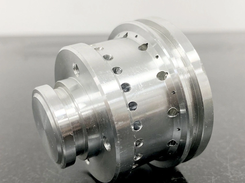
4 Axis CNC milling adds rotation around one axis, often used for radial holes, wrapped features, flats around a cylinder, or side access without repeated manual indexing. 5 Axis CNC milling adds another rotary relationship, which may be used as indexed 3+2 positioning or simultaneous motion. This distinction matters. Indexed machining can be more rigid for many angled features, while simultaneous movement helps sculptured surfaces and changing tool angles. Buyers should ask whether the supplier plans 4-axis, 3+2, or full simultaneous cutting.
2. Complete Multi-Surface Machining in One Setup
Unlike a 3-axis route that often needs re-fixturing to reach another face, a multi-axis route can keep more related features in one datum system. That can reduce alignment error for bores, ports, angled pads, and sealing faces. The advantage is strongest when feature relationships are more important than simple cycle time. It is not automatic. A weak fixture, thin wall, unstable stock, or poor tool access can still create movement and measurement problems. Ask how the part is supported during roughing and finishing.
3. Geometry That Needs Controlled Tool Approach
Multi axis CNC can handle organic shapes, deep cavities, and sculpted surfaces when tool orientation must change to maintain reach and clearance. Typical examples include aerospace turbine blades, robotic actuator housings, and custom medical implants. These parts also need material-specific planning. Titanium can retain heat, nickel alloys can work-harden, and plastics can move after unclamping. The process choice should identify the limiting feature, not just the visual complexity of the model.
4. Tool Engagement and Surface Finish Control
Dynamic tool orientation can reduce tool deflection, improve chip evacuation, and maintain a more consistent contact angle on curved or angled features. Surface finish still depends on cutter type, stepover, material, coolant, vibration, tool wear, and whether polishing or coating follows machining. A fine roughness callout such as Ra 0.4 µm should be tied to a specific surface and measurement method. Buyers should define functional surfaces, cosmetic surfaces, and final inspection state before expecting machining alone to replace secondary finishing.
5. Cycle-Time Improvement When the Route Is Truly Shorter
Multi axis systems can reduce total cycle time when several operations are consolidated and extra reclamping is removed. A percentage saving cannot be assumed without the part geometry, material, fixture, toolpath, and inspection route. Simple 3-axis parts may be faster on a conventional machine because programming and prove-out are lower. Complex multi-face parts may be faster on a multi-axis route even if each toolpath is more advanced. Buyers should compare total manufacturing time, including programming, fixture build, first article inspection, finishing, and documentation.
When to Use Each Technology
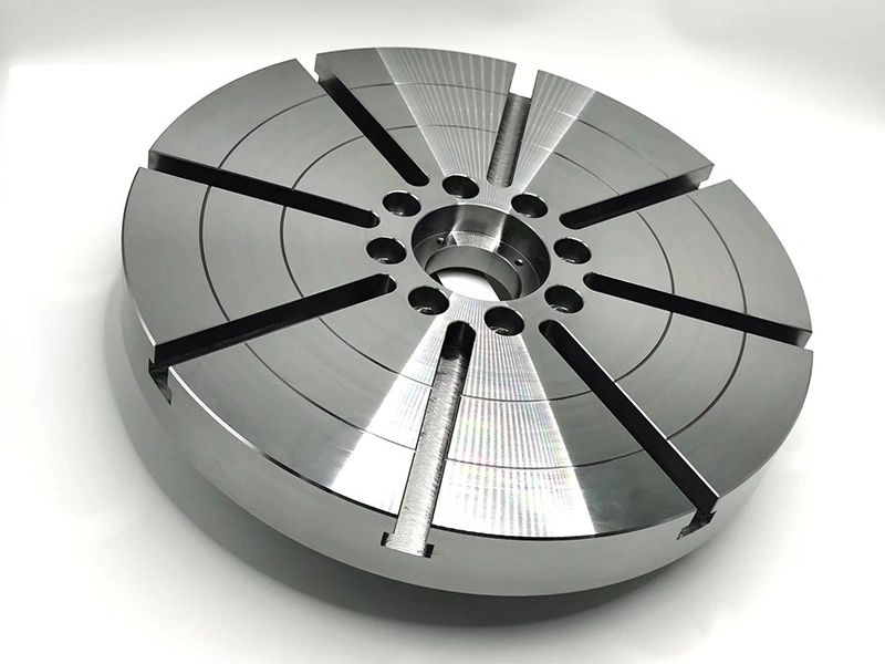
Use 3 Axis Milling for flat parts, open pockets, simple slots, and geometry that can be reached without risky reclamping.
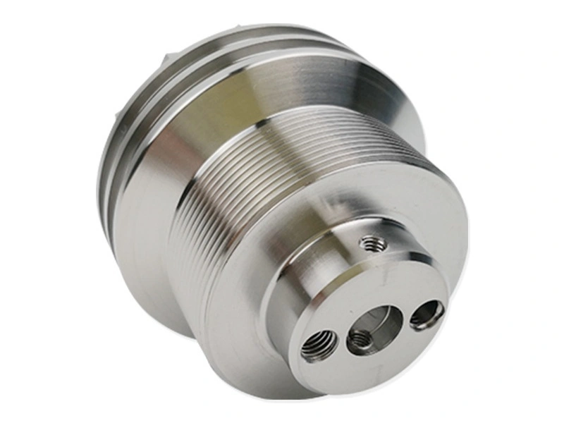
Use 4 Axis Milling for radial holes, cylindrical features, wrapped profiles, and side access around one main rotation.
Use 5 Axis Milling for related multi-face datums, complex surfaces, short-tool access, and features that require angular control.
RFQ Checklist for Comparing CNC Milling Routes
Before choosing Multi Axis CNC Milling, ask the supplier to compare 3 Axis, 4 Axis, and 5 Axis CNC machining against the same drawing. The RFQ should include material grade, stock condition, critical datums, controlled surfaces, tolerance class, finish state, inspection method, and production volume. For aerospace, medical, automotive, and robotics parts, require a route explanation that names the high-risk features. Choose the process that protects function with the fewest avoidable setups, not the process with the highest axis count.