¿Qué precisión dimensional y acabado superficial logra la impresión 3D metálica?
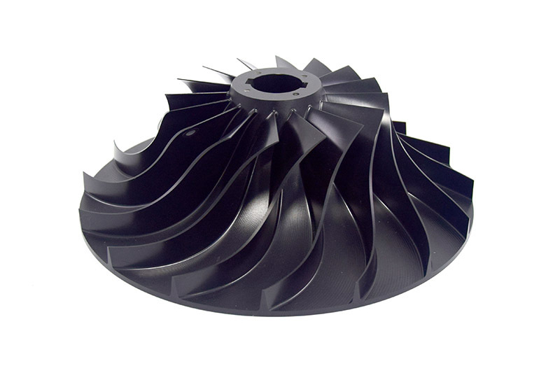
Desde la perspectiva de la ingeniería y la fabricación, la precisión dimensional y el acabado superficial de la impresión 3D metálica, especialmente con tecnologías de fusión en lecho de polvo como DMLS/SLM, son métricas de rendimiento críticas que definen su campo de aplicación. Es esencial comprender que el estado “tal como impreso” representa una línea base, y alcanzar tolerancias de ingeniería finales casi siempre requiere un posprocesamiento complementario.
Precisión Dimensional de las Piezas Tal Como Impresas
La precisión dimensional de una pieza metálica impresa en 3D se refiere a qué tan cerca están sus dimensiones medidas del modelo CAD previsto. Para DMLS, una precisión típica es de ± 0.1 mm a ± 0.2% (lo que sea mayor) en las características críticas en el plano X-Y. La precisión en el eje Z (dirección de construcción) puede ser ligeramente menos consistente.
Factores que Influyen:
Parámetros del Proceso: Potencia del láser, velocidad de escaneo y espaciamiento de trayectorias.
Geometría de la Pieza: Las paredes delgadas y los voladizos son propensos a la distorsión debido al estrés residual.
Material: Diferentes aleaciones (por ejemplo, Aluminio 6061 frente a Inconel 718) tienen distintas características de expansión térmica y fusión.
Posprocesamiento: El alivio de tensiones y tratamientos térmicos como el tratamiento térmico y el HIP pueden inducir pequeños cambios dimensionales.
Comparación con Métodos Tradicionales: La precisión tal como impresa es generalmente menor que la del mecanizado CNC, que puede mantener tolerancias confiables de ± 0.025 mm o incluso más estrictas.
Alcanzar Tolerancias de Precisión con Fabricación Híbrida
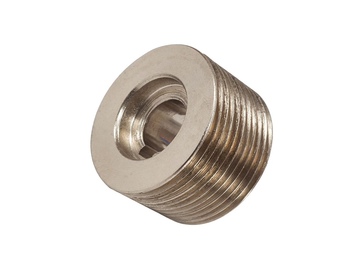
Para componentes que requieren interfaces de precisión, asientos de rodamientos o conexiones roscadas, la precisión estándar tal como impresa es insuficiente. Aquí es donde un enfoque híbrido resulta esencial.
Mecanizado CNC Secundario: Las características críticas se imprimen intencionalmente con exceso de material (margen de mecanizado) y luego se terminan con tolerancias ajustadas mediante servicios de mecanizado de precisión como fresado CNC o torneado CNC. Esto combina la libertad geométrica del DMLS con la precisión dimensional del CNC.
Tolerancias Realistas: A través de este método, se pueden lograr tolerancias de ± 0.025 mm a ± 0.05 mm (grados IT 7-9) en las características especificadas, haciendo que las piezas sean adecuadas para aplicaciones exigentes en aeroespacial y dispositivos médicos.
Acabado Superficial de las Piezas Tal Como Impresas
El acabado superficial de una pieza DMLS tal como impresa se caracteriza por cierta rugosidad debido a las partículas de polvo sinterizadas. Un rango típico es de Ra 10 - 25 μm (400 - 1000 μin), lo que produce una textura rugosa.
Causas de la Rugosidad:
Partículas Parcialmente Sinterizadas: Las partículas finas de polvo se adhieren a la periferia del baño de fusión.
Efecto de “Escalones”: La naturaleza capa por capa crea una textura escalonada en superficies curvas o inclinadas.
Marcas de Estructuras de Soporte: Los puntos donde los soportes contactan la superficie dejan imperfecciones.
Impacto Funcional: Esta superficie rugosa tal como impresa generalmente no es adecuada para superficies de rodamiento, sellos de fluidos o aplicaciones críticas por fatiga, ya que puede actuar como punto de concentración de tensiones.
Mejorar el Acabado Superficial mediante Posprocesamiento
Se emplea un conjunto de técnicas de posprocesamiento para mejorar el acabado superficial, cada una con diferentes capacidades y resultados.
Chorreado Abrasivo: El arenado es un primer paso común que limpia la superficie y reduce la rugosidad máxima, logrando típicamente un Ra 4 - 8 μm. Crea un acabado mate uniforme.
Acabado Vibratorio: El pulido por tamboreo es excelente para redondear bordes, eliminar rebabas y producir un acabado más suave y semimate, mejorando el Ra a alrededor de Ra 1 - 4 μm.
Mecanizado por Flujo Abrasivo (AFM): Eficaz para pulir canales internos y geometrías complejas que son inaccesibles mediante otros métodos.
Electropulido: Este proceso electroquímico es altamente eficaz para lograr un acabado suave y micropulido. El electropulido puede mejorar el acabado superficial hasta Ra 0.2 - 0.8 μm y además mejora la resistencia a la corrosión.
Mecanizado/Rectificado CNC: Para el mejor acabado superficial posible en superficies planas o cilíndricas críticas, se utiliza el rectificado CNC o el mecanizado tradicional. Esto puede alcanzar acabados de Ra 0.4 μm o mejor, equivalente a un acabado tal como mecanizado de alta calidad.
Resumen de Especificaciones Alcanzables
Característica | Tal Como Impreso (DMLS) | Con Posprocesamiento |
|---|---|---|
Precisión Dimensional | ± 0.1 mm a ± 0.2% | ± 0.025 mm (en características mecanizadas) |
Acabado Superficial (Ra) | 10 - 25 μm | 0.2 - 4 μm (dependiendo del método) |
Guías de Ingeniería para el Diseño
Diseñar para el Proceso: Tenga en cuenta las limitaciones del estado tal como impreso en su diseño, evitando tolerancias críticas en superficies internas de difícil acceso.
Especificar Características Críticas: Defina claramente qué superficies requieren tolerancias estrechas y acabados finos para que pueda aplicarse un margen de mecanizado para el procesamiento secundario.
Considerar Todo el Flujo de Trabajo: La ruta óptima para una pieza de alta precisión a menudo implica impresión 3D de la forma compleja casi neta y el uso de mecanizado CNC para lograr la precisión final.