Superalloy CNC Machining Parameters: Key Factors for Success
Introduction: The Decisive Role of Parameter Optimization in Superalloy Machining
Superalloy CNC machining parameters decide whether a part keeps its required size, surface integrity, tool-life stability, and material performance after cutting. The challenge is not only that superalloys are strong. Nickel-based and cobalt-based alloys also hold heat near the tool, resist shearing, work-harden after rubbing, and can form difficult burrs around holes and thin edges. In providing superalloy CNC machining services, parameter planning should connect cutting speed, feed, depth of cut, tool geometry, coolant delivery, machine rigidity, and inspection. Buyers should not request a generic CNC quote for these parts. A strong RFQ gives alloy grade, material condition, critical surfaces, tolerance class, surface requirement, heat-treatment stage, and the feature that controls acceptance.
Parameter optimization is a controlled engineering decision, not a search for the fastest possible cycle. A higher speed can reduce cycle time but raise cutting temperature. A lower feed can look safe but cause rubbing and work hardening. A deeper cut can remove stock faster but deflect a thin wall or overload a long tool. The useful decision asks which failure mode is most likely for the part: tool wear, chatter, chip packing, tensile residual stress, burr growth, dimensional drift, or surface damage. This article stays inside that boundary. It explains how to select and validate CNC parameters for superalloy parts, while leaving alloy selection and full life prediction to separate material and design reviews. The final quote should separate starting parameters, validated first-article parameters, and production control limits. Those are different decisions. Ask for the validation evidence behind each parameter window.
Core Parameter I: The Art of Balancing Cutting Speed
Cutting speed sets the heat level at the tool-workpiece interface and strongly affects tool wear in superalloys. For carbide roughing of Inconel 718, a conservative starting range is often around 20 to 40 SFM, or about 6 to 12 m/min, when setup rigidity and coolant delivery are uncertain. Higher speeds may be validated for light finishing, ceramic tooling, or stable continuous turning, but those cases require separate tool and setup confirmation. The buyer action is to ask whether the quoted speed is a starting value, a proven production value, or only a catalog recommendation.
Cutting speed should be validated through chips, tool edge condition, surface appearance, and measured size. Blue or purple chips can point to high heat, but chip color alone is not a complete approval method. Powdery chips, welded chips, dark rough chips, or sudden chip-length changes can show rubbing, poor chip evacuation, or unstable engagement. For heat-resistant alloys, a tool can fail by notch wear at the depth-of-cut line before general flank wear looks severe. A good first-article review records speed, feed, depth of cut, coolant method, insert grade, chip behavior, tool wear, and the feature measured after the cut. If the part has multiple critical features, the speed may need local limits by feature instead of one page-wide value.
Precision machining services should use different speed logic for roughing, semi-finishing, and finishing. Roughing needs stable chip formation and predictable tool life, while finishing needs size control, low burr risk, and surface integrity. For Inconel 625, work hardening and corrosion-service surfaces make overheating and rubbing especially costly. The final speed should therefore be tied to the function of the surface. A sealing land, fatigue-loaded radius, or coated surface may justify a slower, cleaner final pass even when a faster value removes material successfully.
Core Parameter II: Precise Control of Feed Rate
Feed rate controls chip thickness, cutting force, surface marks, and how much heat leaves with the chip. In superalloy machining, the feed must be high enough to cut instead of rub, but low enough to keep force within the limit of the tool, fixture, and feature. This is why “small depth of cut, larger feed” can be useful only when it is treated as a conditional strategy. If the wall is thin, the tool is long, or the holder is unstable, the same feed can bend the part. Feed approval should use evidence from chip shape, sound, machine load, tool wear, burrs, and measured features.
For CNC milling services, feed per tooth may start from a conservative tool-supplier value and then be adjusted through controlled test cuts. Corners, slots, and pockets need special attention because engagement can rise suddenly. A stable straight cut does not prove the same feed is safe at a tight internal corner. Toolpath smoothing, corner slowdown, constant-engagement milling, and coolant direction all affect feed choice. For Hastelloy X, the feed should promote real shearing and chip evacuation without leaving burr roots or heat-damaged surfaces. The inspection record should include burr condition at entries, exits, and intersections, because feed problems often appear first at edges.
Finishing feed needs separate validation because the last pass controls the surface that the buyer receives. For Waspaloy, notch sensitivity, high strength, and aging condition can make surface marks and burrs more important than cycle time. A finish feed should be checked against roughness, profile, roundness, hole quality, and edge-break requirements. If polishing, coating, or heat treatment follows machining, the feed must leave enough material and surface quality for that next step. The RFQ should specify whether roughness is cosmetic, sealing, fatigue-related, or coating-preparation related.
Core Parameter III: Strategic Selection of Depth of Cut
Depth of cut determines force direction, chip load, heat generation, and whether the tool cuts below a work-hardened layer. A shallow cut is not automatically safe. If the depth is too small, the edge may rub the hardened surface instead of shearing cleanly. A deep cut is not automatically productive either, because tool deflection, fixture movement, or chip packing can destroy repeatability. The selected radial and axial depth should match tool diameter, edge preparation, machine power, holder rigidity, wall thickness, and chip evacuation. Roughing should leave a known finishing allowance rather than chasing the final size too early.
In CNC turning services, depth of cut must stay consistent enough to avoid rubbing in hardened layers and sudden load shifts. High-strength alloys such as Rene 41 need tool engagement that is deep enough to cut cleanly, but not so deep that heat and force overload the edge. Thin-wall turning often needs smaller depths, balanced stock removal, and inspection after unclamping. The buyer should mark thin sections, datum surfaces, and final wall requirements so the process can separate roughing, stress relief, semi-finishing, and final finishing.
Deep cavities need a depth strategy that protects chip flow and holder stiffness. In multi-axis machining services, tool orientation can reduce overhang, improve coolant access, and keep engagement more stable across complex surfaces. Step-down machining may be useful, but the actual axial depth must still be matched to tool length, flute design, pocket width, and chip evacuation. A common failure mode is packing chips in a corner, then recutting them into the wall. Validation should include surface review in deep features, not only top-level dimensional checks. If a bore or pocket will be coated, the depth strategy must also leave allowance for final coating thickness and cleaning access.
Key Factor I: Tool Selection and Geometry
Tool selection must match the superalloy, material condition, feature geometry, and cooling method. Fine-grain carbide with suitable coatings may be used for many nickel alloy operations, but the coating and substrate must survive heat, notch wear, and interrupted engagement. When machining Haynes 282, tool sharpness, edge strength, and heat resistance all matter because the alloy is used for high-temperature strength. A larger rake angle can reduce cutting force, but an overly weak edge can chip. The process plan should identify whether the controlling risk is force, edge wear, chatter, or surface integrity.
Tool geometry also defines how parameters behave in the real cut. Positive rake can reduce force, nose radius can influence finish and edge strength, and helix angle can affect chip evacuation. In CNC drilling services, point angle, web thinning, flute shape, through-tool coolant, and pecking strategy all influence hole quality. A diameter check alone cannot prove that a superalloy hole is durable. Bore finish, exit burrs, chip scratches, straightness, and coolant-through cleaning may need inspection. The RFQ should state whether the hole is threaded, sealing, pinned, pressure-flow, or fatigue loaded.
Key Factor II: Coolant and Cutting Temperature Management
Coolant strategy should be selected for the heat and chip problem being solved. High-pressure coolant around 70 to 140 bar is often reviewed for titanium and superalloy work, while deeper holes may need a higher range when chip evacuation is the main failure mode. Pressure is not enough by itself. Flow rate, nozzle aim, through-tool channels, filtration, coolant concentration, and port blockage can decide whether coolant reaches the cutting edge. A buyer should ask for pressure at the tool and the planned coolant delivery method, not only the pump rating. Useful trial evidence includes chip evacuation, coolant temperature trend, tool wear, hole cleanliness, surface roughness, and burr condition.
Coolant chemistry and cleaning also affect process stability. Concentration and pH should be controlled within the coolant supplier's recommended range for the alloy, machine, and environmental requirements. In CNC grinding services, coolant delivery is especially important because grinding burn, tensile stress, and thermal cracks can appear when heat is not removed. The inspection plan should look for burn marks, roughness drift, surface cracking, and dimensional change after cooling. If later coating or electropolishing is planned, coolant residue and surface condition should be included in cleaning validation.
Key Factor III: Machine Tool Performance and Stability
Machine rigidity and dynamic response place a real limit on cutting parameters. Static stiffness, spindle torque, holder quality, axis motion, thermal drift, and fixture design all decide whether the selected speed and feed can be repeated. Numeric machine specifications should not be treated as finished-part tolerance promises. In EDM services, machine stability affects discharge consistency, recast layer, and surface damage rather than chip load. The same principle applies across processes: equipment capability must be connected to part geometry, inspection method, and acceptance criteria.
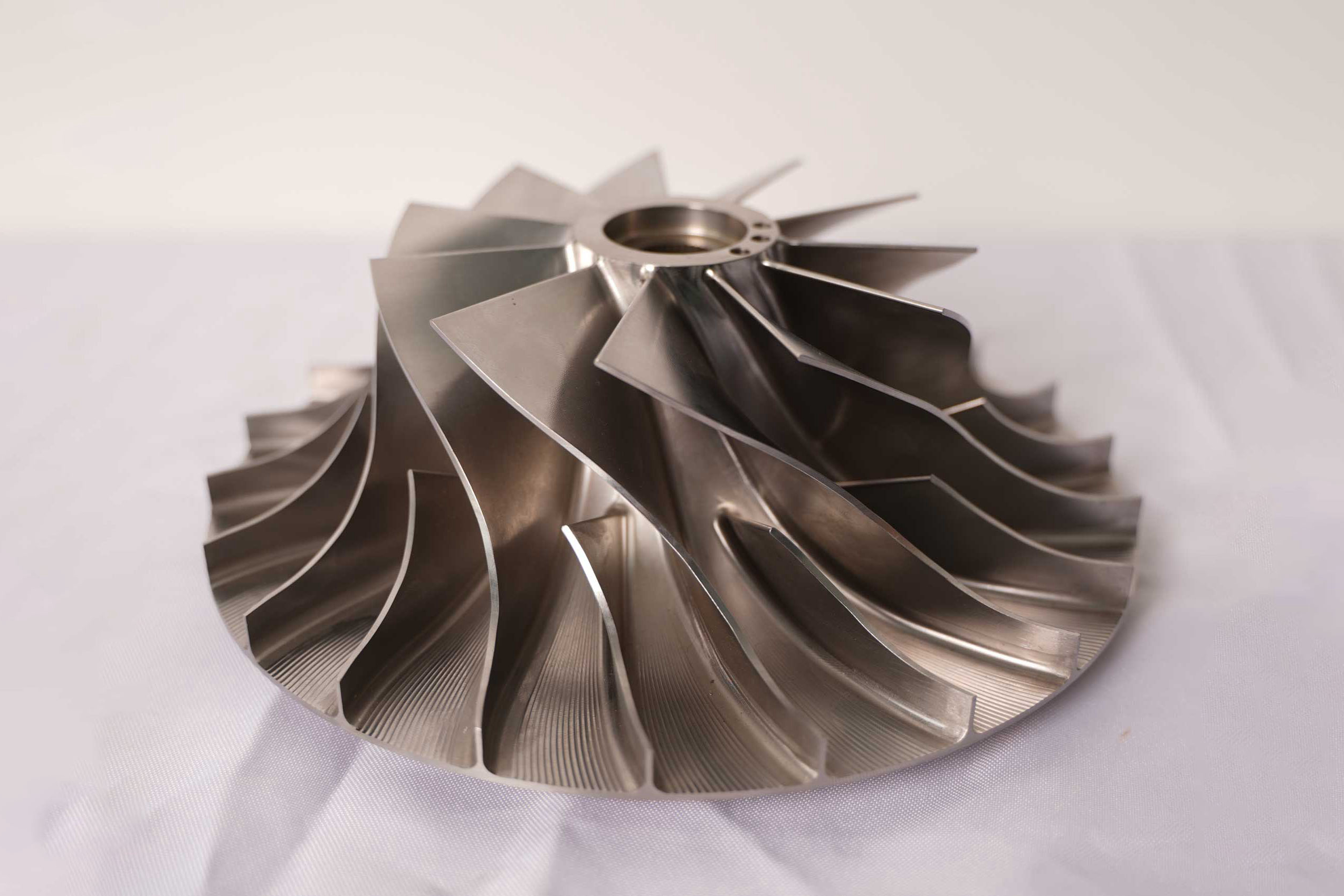
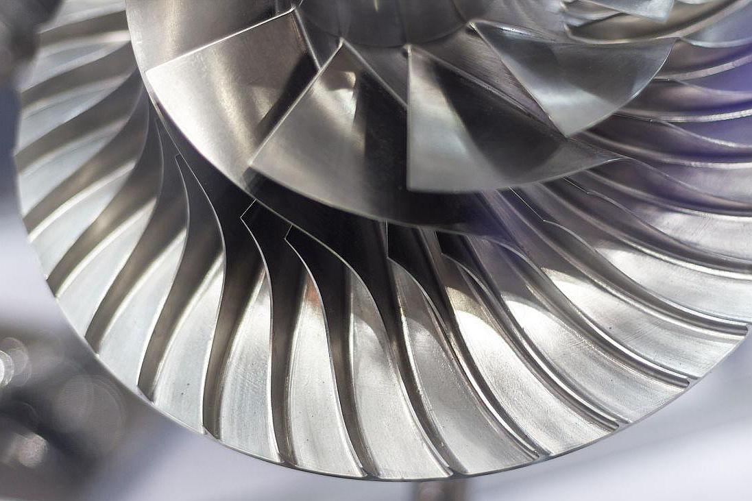
Five-axis and high-speed machining add another parameter layer because tool orientation changes engagement, contact length, and coolant access. Repeatability matters, but acceleration, jerk, rotary axis motion, and look-ahead control can affect surface quality just as much. Complex impellers, casings, and thin ribs need parameter review by region rather than one global feed value. The process sheet should identify high-load corners, long-reach tools, thin-wall passes, and features measured after unclamping. This makes parameter control visible to purchasing and quality teams instead of hiding it inside CAM programming.
Key Factor IV: Process Path and Programming Strategy
Toolpath strategy determines whether nominal parameters remain stable during the actual cut. Trochoidal milling, helical interpolation, ramp entry, adaptive clearing, and constant-engagement paths can reduce load spikes when the geometry supports them. In low-volume manufacturing services, the first few parts are useful for validating engagement, burr behavior, tool-change timing, and inspection access. The supplier should not freeze production parameters until the first article shows stable chips, size, surface condition, and tool wear. If the part is expensive, process validation may save more than a shorter programmed cycle.
Climb milling often improves tool life and finish, but it is not a universal rule. Scale, hardened skin, thin walls, fixture compliance, and interrupted surfaces can change the best strategy. Conventional milling may be used selectively when it protects an edge or handles an existing surface condition better. In mass production services, the question is not only which path is fastest. The buyer should ask whether tool life, burrs, machine load, and last-part-before-tool-change inspection remain stable across the lot. Repeatability is the value of parameter optimization in production.
Practical Application of Parameter Optimization and Case Studies
A practical aerospace-style parameter problem often involves a heat-resistant casing, bracket, or ring where aerospace requirements combine thin sections, tight datums, and fatigue-sensitive edges. A useful process plan would rough in balanced stages, leave finishing allowance, verify movement after unclamping, then finish critical datums with conservative feed and coolant access. For oil and gas valve bodies, the main parameter risk may be deep-hole chip packing, burrs at intersections, or seal-land finish. These two examples use different parameter priorities, even when both parts are machined from heat-resistant alloys. This is why a parameter sheet should name the controlling feature, not only list speeds and feeds.
For power generation equipment, thermal cycling and surface integrity can be more important than removing stock quickly. Blade roots, seal features, and hot-gas-path hardware may need separate finishing parameters, burr controls, and inspection hold points. The buyer decision is to identify the surface that controls function before quoting. If the only requirement is a 3D model and a material name, the supplier may optimize for machining efficiency instead of service risk. Better RFQ data allows the process to protect the features that actually determine durability. A useful RFQ also states whether the part will be inspected after heat treatment, after coating, or after final cleaning. It should define who approves any parameter change after first-article acceptance.
Neway’s Parameter Optimization Practice and Professional Services
Neway's one-stop service model is useful when parameter optimization must connect machining, heat treatment, surface finishing, inspection, and documentation. During prototyping services, the process can test cutting speed, feed, coolant, tool wear, fixture stability, and burr control before production. During CNC prototype manufacturing, the first-article record should capture the real parameter window, not only the final drawing dimensions. This helps buyers decide whether to adjust the design, change the inspection plan, or approve the process for repeat parts.
For the industrial equipment sector, parameter optimization often starts with practical failure modes: sealing leakage, bore burrs, thread damage, vibration marks, or distortion after heat treatment. A supplier review should connect each failure mode to a parameter and a verification method. If burrs control assembly, feed and tool wear may matter more than headline speed. If flatness moves after unclamping, fixture pressure and roughing sequence need review. This is the kind of engineering detail that should appear in the RFQ discussion before purchase approval.
In the nuclear industry, parameter control must be documented with the required code, inspection plan, and traceability level defined by the buyer's specification. Machining parameters alone do not prove compliance. The process may also need coordinated heat treatment services or electropolishing services, depending on material, surface condition, and final environment. A complete RFQ should define material standard, heat number traceability, critical dimensions, NDT or surface inspection, post-process sequence, and acceptance documentation before production begins. It should also define which process data must be retained, such as first-article parameters, tool-change records, coolant settings, inspection reports, and deviation approvals. That record makes parameter control traceable instead of informal. Final acceptance should state which dimensions are checked before and after each post-process step.
FAQ
What cutting speed range is typically used as a starting point when machining Inconel 718?
How can I determine whether the current feed rate is appropriate?
What pressure level is generally required for high-pressure coolant systems?
To what extent can a tool be worn before it must be replaced?
What considerations are needed when setting parameters for thin-walled superalloy components?