Precision CNC Grinding Services: Surface Integrity, Geometry, and Inspection
Precision CNC Grinding Services: Surface Integrity, Geometry, and Inspection
Precision CNC grinding services should be selected by the surface, geometry, material state, and inspection evidence the finished part requires. Grinding is not a universal precision upgrade: it can improve a defined surface or relationship when stock, support, thermal control, wheel condition, and measurement state are planned together. Buyers should identify the characteristic at risk, the pre-grind condition, the post-grind acceptance method, and the record needed for release. A precision grinding route review is useful when it explains those controls rather than promising a generic finish.
Define the Grinding Objective
Start by naming what grinding must change: flatness, parallelism, cylindricity, a bearing surface, a seal land, a controlled roughness, or a relationship to an established datum. State the functional consequence and the evidence that can demonstrate it. If grinding is proposed only because the word “precision” appears in a requirement, pause and identify the actual characteristic. A secondary process without a defined purpose can remove useful stock, alter a datum, or add cost without improving function.
Separate geometric objectives from appearance. A uniform visual texture does not prove roughness, flatness, or form. A measured roughness does not prove position or assembly fit. Define each acceptance field and its method. If the part will be coated, cleaned, heat-treated, or assembled after grinding, include those state transitions in the plan.
Use the Image as a Geometry Prompt
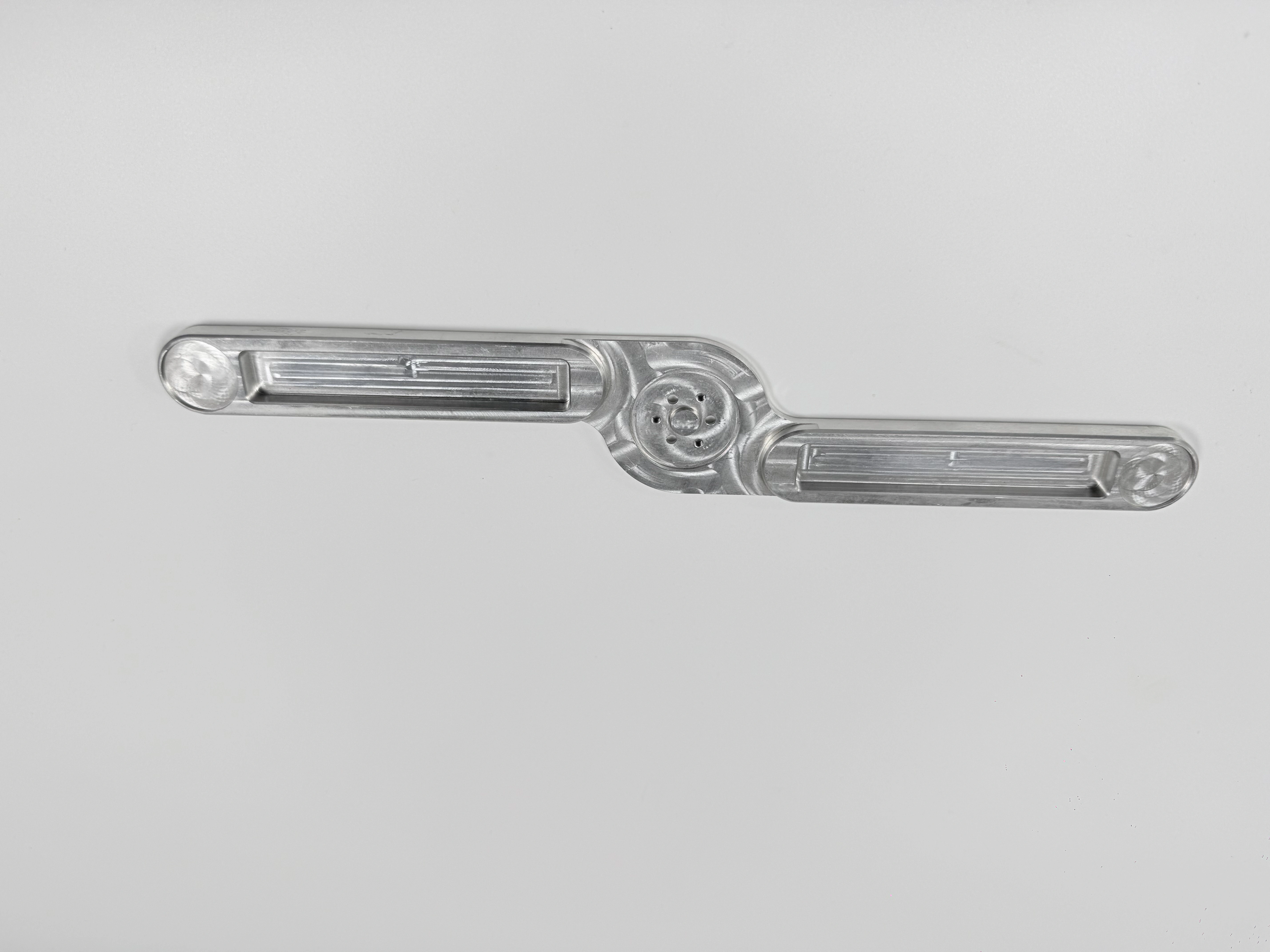
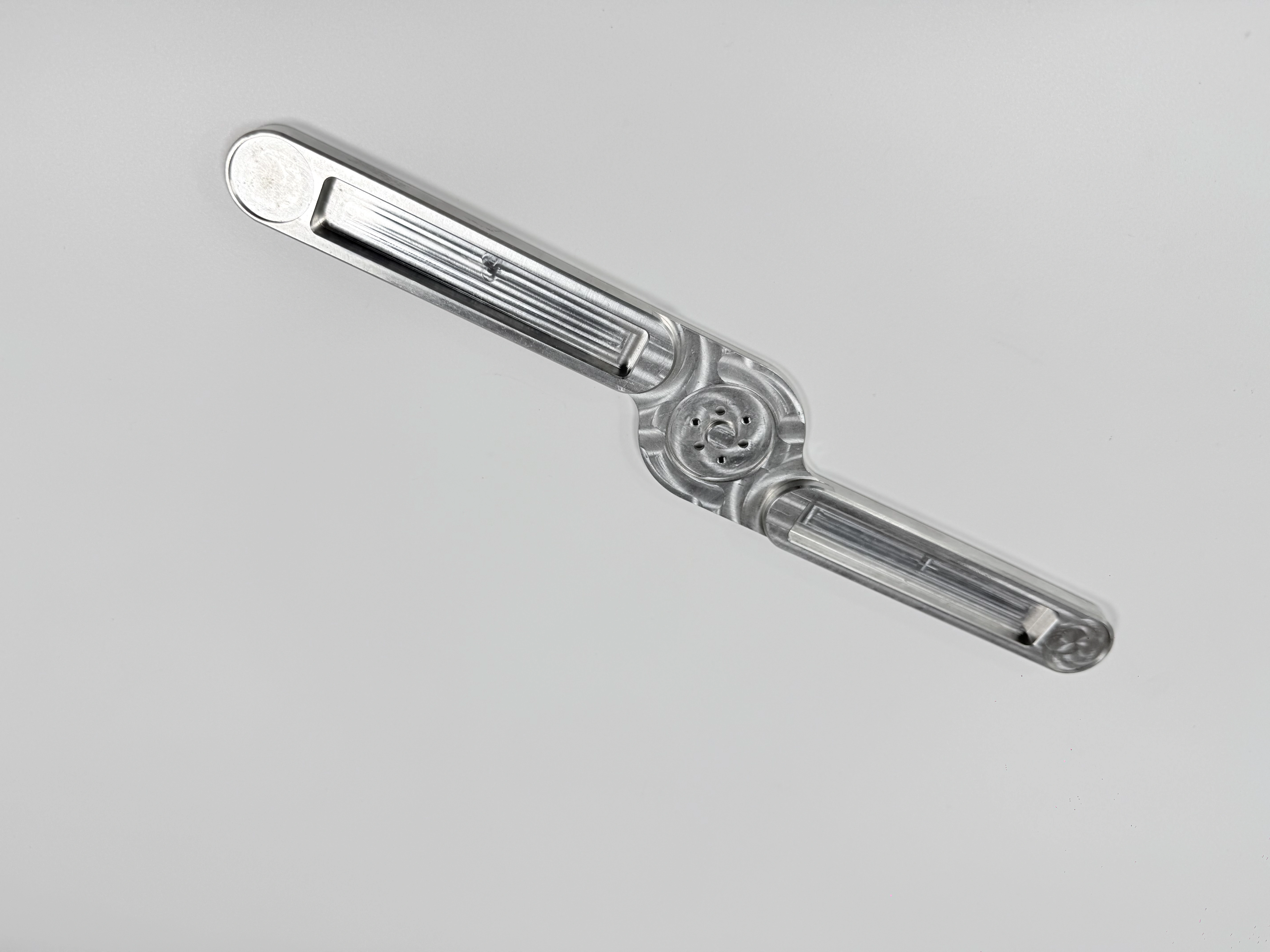
The paired images show a long machined link arm with two recessed channels, a central circular region, and rounded ends. The views confirm one physical component and different angles. They do not reveal material grade, hardness, stock, load, tolerance, roughness, or application. Use the component to ask which face is functional, where a grinding wheel could reach, and how the central feature is referenced; use the drawing and process record to control the answer.
Plan Allowance Before the Grinding Operation
Grinding needs enough stock to remove the expected variation without creating unnecessary heat or cycle time. State rough-machined size, allowance, datum condition, and the operation that leaves the stock. Excess stock can increase thermal load, wheel wear, and distortion; insufficient stock can leave a surface that cannot be corrected. The allowance should be tied to the actual material, support, and previous process.
Record whether the part is stress-relieved, heat-treated, or stabilized before grinding. A material certificate supports identity within scope; it does not prove final geometry or hardness after processing. If the material state changes after roughing, define the measurement and allowance review before finishing.
Assign Allowance by Feature
Different features may need different stock. A broad reference face, a narrow channel floor, and a cylindrical interface can react differently to support and heat. Map each CTQ to the operation that establishes it and the measurement that confirms it. Do not infer an allowance from a photograph or a general material table without a part-specific review.
Control Thermal and Mechanical Effects
Grinding energy can change surface temperature, residual stress, and form if wheel, coolant, feed, dress condition, or support is not controlled. State the coolant or dry condition, workholding, pass strategy, and dressing trigger where they affect the characteristic. A surface that looks uniform may still have a thermal or stress-related issue that appears after release or assembly.
Support state matters for thin or flexible geometry. Define whether the feature is measured restrained, free, or assembled, and whether it is ground in the same state. If a clamp or support is changed, identify affected CTQs and recheck. The machine specification alone does not prove the finished surface or geometry.
Write a Thermal Reaction Rule
Set a reaction when discoloration, burn, unexpected distortion, roughness change, or drift appears. Hold the affected units, identify the time range and wheel state, and decide whether rework, replacement, expanded inspection, or an approved deviation is appropriate. Preserve the original result and the process condition; do not overwrite a failed record with a corrected value.
Establish a Datum Strategy That Survives Reorientation
Grinding often follows milling, turning, or heat treatment, so datum transfer must be explicit. State which surface or feature establishes the reference, how it is located, and how the transfer is verified. A datum that is convenient for fixturing may not be the datum that governs assembly. If a secondary operation changes the surface, record the before-and-after relationship.
When the central circular region or a recessed channel is functional, identify its alignment to the datum and the support used during measurement. A CNC machining route review can frame the preceding operation, while a boring reference can frame an internal relationship. Neither page replaces the controlled drawing or measured transfer.
Check Datum Transfer
Use a transfer check after a new fixture, reorientation, or process change. Identify contact order, support, clamp direction, locator condition, and measurement alignment. If a replacement contact is installed, record its identifier and qualification. A fixture can hold a part securely while still shifting a positional relationship if the datum chain is not documented.
Select Wheel and Process Controls From the Material
Wheel selection, dressing, speed, feed, depth, coolant, and pass sequence should be tied to the material designation, condition, geometry, and required surface. Do not write a universal parameter or wheel-life promise without evidence. State what the supplier may adjust, what requires approval, and how the change is verified.
For aluminum, stainless, hardened, or coated parts, a material machining reference or stainless-steel route can frame questions about loading, heat, or burrs. These references do not prove a specific wheel, condition, or surface result for the pictured link arm.
Monitor Wheel Condition
Use a measurable dressing or replacement trigger such as count, surface response, load trend, or observed form drift. Record wheel identifier, installation, dressing, affected lot, and the first check after a change. A wheel that is visually intact may still load or lose form. Keep the boundary between routine dressing and a process change clear.
Protect Surface Integrity and Edge Conditions
Define roughness, waviness, edge break, burr, burn, and handling limits in the drawing or specification. A surface-finish reading applies to the stated cutoff, direction, location, and instrument; it does not prove every area. If a channel floor or rounded end is functional, identify sampling locations and the support state. If a mark is cosmetic only, separate it from a functional acceptance rule.
Cleaning and packaging can change what the buyer receives. State whether the surface is measured before or after washing, coating, or protective treatment. A finish reference can clarify texture language, but the specified measurement method remains controlling.
Review Surface Failure Modes
List loading, burn, chatter, pull-out, embedded abrasive, burr, corrosion, and handling damage as possible failure modes when relevant. For each, identify detection and containment. Do not treat a polished appearance as evidence that the surface is free of thermal or geometric defects.
Measure Geometry and Surface With Separate Evidence
Dimensional, form, location, roughness, and functional results need their own methods and states. A CMM can report location or form in a defined alignment; a roughness instrument reports a sampled texture; a gauge can demonstrate a fit; a visual check can identify a mark. None should be described as proving the others. Record units, datum, instrument, calibration status, support, temperature, sample identity, and revision.
Measure the first unit before a full lot when allowance, support, or wheel condition could invalidate the route. Repeat affected checks after a tool, fixture, wheel, coolant, material, or sequence change. If a result is missing or belongs to another state, contain the unit and document the disposition.
Use an Inspection Evidence Table
| Characteristic | Method and state | Boundary |
|---|---|---|
| Flatness or form | Defined alignment, support, and instrument | Not assembly or roughness proof |
| Roughness | Location, direction, cutoff, and gauge | Not all-area finish proof |
| Position | Datum frame and unit identity | Not material or load proof |
| Function | Mating hardware, load, or cycle | Not unmeasured geometry |
The table keeps evidence bounded. A quality inspection planning reference can organize ownership, but the drawing defines acceptance.
Plan the measurement sequence around the way the part is supported. A long link arm may be checked on a stable reference face, then released to see whether elastic recovery changes the central circular region or the channel relationship. Record both states only when the drawing or function requires them, and state which state controls release. Do not average restrained and free readings into one value; they answer different questions about fixture influence and delivered behavior.
Measurement uncertainty should be visible at the decision boundary. Identify the method resolution, repeatability study or correlation basis, probe access, temperature, and alignment choices that can move the result. If a result is near a limit, retain the raw data and ask the quality owner whether a guard band or additional measurement is required. A narrow numerical margin is not evidence of process capability when the method cannot resolve the feature or the support state is uncontrolled.
Use a feature-risk map to choose inspection frequency. A surface that controls a seal, bearing, or sliding relationship may need every-unit evidence, while a nonfunctional appearance zone may be sampled under an approved plan. The map should name the failure consequence, the detection method, the responsible owner, and the reaction. This keeps sampling proportional to risk without claiming that one convenient trace represents the entire component.
When grinding is combined with milling or turning, preserve the handoff between operations. Record which operation establishes each datum, which operation leaves stock, and which operation owns the final characteristic. If an upstream change alters the entry condition, trigger an allowance and support review before the wheel is dressed for production. A stable finishing cycle cannot compensate for an undocumented datum or an unstable preceding route.
Route selection should also account for the work that surrounds grinding. A turning process reference helps define the cylindrical stock and axis handoff; a milling process reference helps define accessible faces and interrupted features. Where a bore or bearing interface is involved, a boring process reference frames axis evidence, while a metal finishing reference frames cleaning and post-grind handling. These pages can organize the question set, but none replaces the controlled drawing, feature-specific allowance map, or lot-linked inspection record.
Control Process and Tool Life
Use a control plan that identifies wheel, dressing, coolant, support, measurement frequency, sample identity, owner, and reaction. Tool or wheel life should use a measurable trigger, not a universal count. When the trigger is reached, identify affected CTQs and perform the required check before continuing.
Keep process data tied to material heat, revision, fixture, operator or owner, and lot. If a trend appears, contain the affected range and investigate thermal, wheel, support, and measurement causes. A stable trend under one condition does not guarantee another material or state.
Control Outside Processes and Delivered State
Heat treatment, coating, cleaning, passivation, and packaging can alter a ground surface or dimension. State processor, specification, batch, masking, before-and-after checks, and certificate linkage. A certificate supports the processor claim within scope; it does not replace final-part measurement or functional evidence.
If the part is assembled after grinding, define contact surfaces, fastener condition, load, and acceptance. The delivery record should distinguish as-ground, coated, cleaned, and assembled states. A visual image cannot prove any of those conditions.
Review State Transitions
When a state transition is proposed, identify the affected CTQs, record owner, and recheck. If the delivered state differs from the measured state, hold the lot until valid evidence exists. Keep original and post-process results together.
Plan the disposition path before a ground feature is found out of trend. A small dimensional drift may be corrected only when enough stock, a valid datum, and an approved rework route remain; a thermal indication or uncertain surface history may require containment instead of another pass. Define who can authorize regrinding, which measurements must be repeated, and how the original unit identity stays attached. This prevents a visually improved part from losing the evidence needed to judge surface integrity, form, or downstream fit.
Write an RFQ That Makes Grinding Comparable
Attach the controlled drawing and model, revision, material and condition, stock and allowance, datum, CTQs, roughness, edge, cleaning, outside processing, support state, inspection method, sampling, records, packaging, and milestones. Ask suppliers to state wheel/process assumptions, dressing trigger, fixture, access, thermal controls, inspection ownership, and known limitations.
Separate setup, wheel qualification, programming, first-piece, inspection, recurring conversion, outside processing, packaging, and freight costs. Request notification before material, wheel, fixture, program, coolant, process, inspection method, processor, or packaging changes. A turning reference may help compare a preceding route, but the RFQ remains the acceptance scope.
Screen the Grinding Supplier on Evidence
Compare whether each candidate explains allowance, datum transfer, wheel and coolant controls, fixture support, thermal reaction, measurement state, surface evidence, outside-process handoff, and change notification. A machine list, wheel brand, or generic roughness claim is not proof for this geometry.
Ask for an anonymized process, inspection, or reaction format tied to comparable features. Choose the response that states limitations, owners, sample basis, and evidence. It should identify what is measured, what is sampled, what is functional, and what requires approval.
Release the Ground Lot With Explicit Boundaries
Release when revision, material state, allowance, datum, process record, wheel condition, geometry, surface evidence, functional checks, outside-process certificates, packaging, and deviations agree. Hold when a result is missing, belongs to another state, or cannot be traced to the lot. Grinding improves a defined characteristic only when the evidence supports that claim.
The strongest precision CNC grinding decision connects objective, stock, thermal control, datum transfer, wheel condition, inspection, and delivered state. Use the pictured link arm as a geometry prompt, not a capability claim. Let the controlled drawing, process response, and lot-linked records determine acceptance.
FAQ