Which Roughness Evidence Supports a Ground Surface?
Which Roughness Evidence Supports a Ground Surface?
Roughness evidence supports a ground surface only when the trace location, direction, cutoff, instrument, calibration, surface state, and acceptance criterion are identified. A single numerical value or a polished appearance is not a universal proof for every face. Grinding can produce directional texture, local loading, waviness, burrs, or embedded abrasive that a convenient trace misses. The buyer should define which surfaces are functional, how they are sampled, and what the result does not prove before accepting a report.
Separate Roughness From Other Surface Terms
Roughness describes a measured component of texture under a stated method. Waviness, form, lay, edge break, burr, burn, pull-out, and contamination are different conditions. An Ra value cannot establish flatness, roundness, residual stress, hardness, or assembly performance. If a seal land needs both a texture limit and a form limit, list both requirements and assign a method to each. Do not let a supplier use one finish number as a substitute for the complete surface specification.
Choose Locations That Represent Function
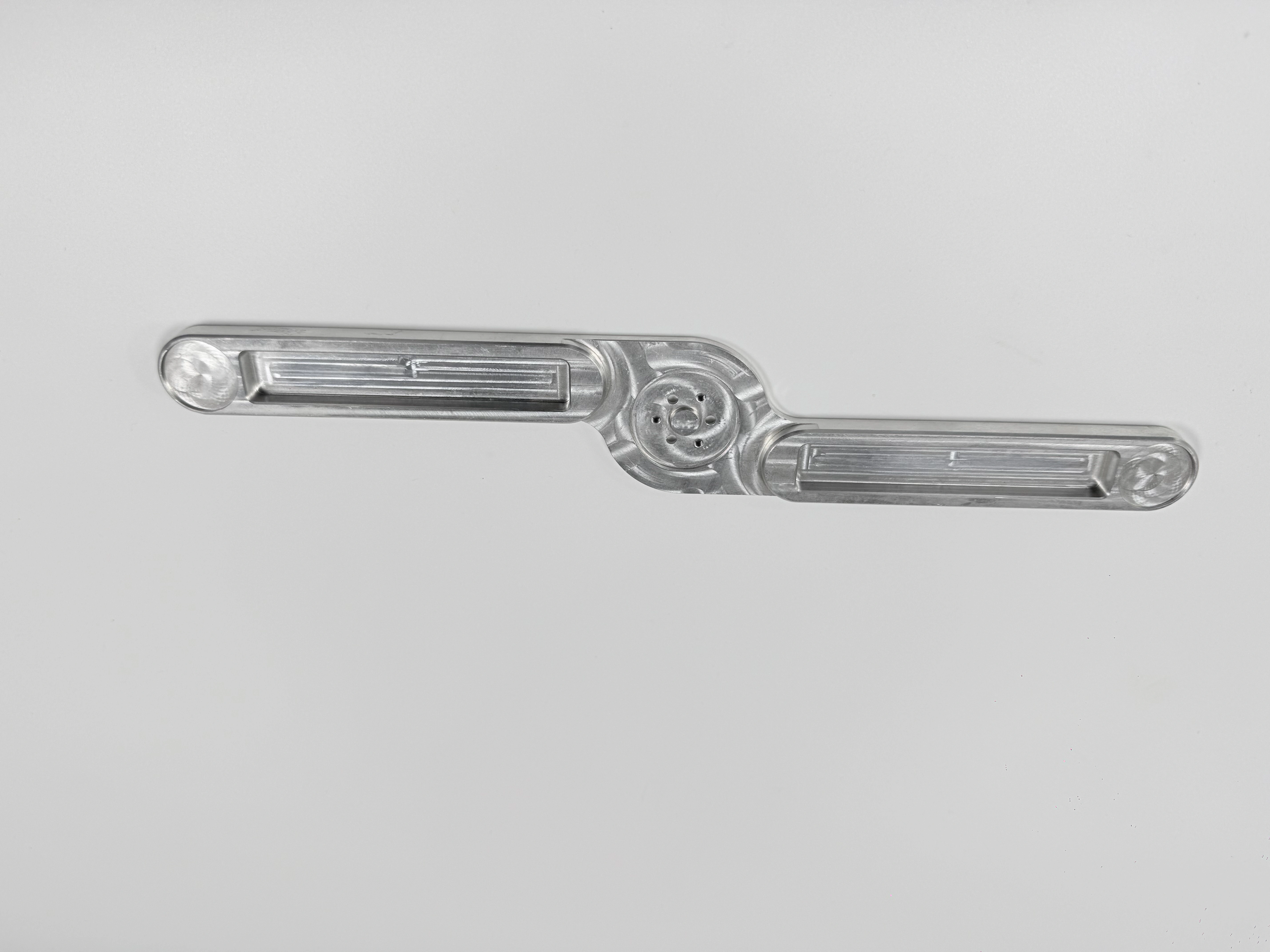
Map each required trace to a functional zone. On a long link arm, a broad face, a recessed channel floor, a rounded transition, and the central circular region can have different wheel contact, access, and support. A trace on the broad face does not represent a narrow recess. A trace near an edge can include an edge break instead of the intended surface. Mark locations on the drawing or inspection plan and use a repeatable orientation.
Control Direction and Lay
Align the instrument according to the specified or functionally relevant direction. A grinding lay can make readings change when the stylus crosses or follows the texture. For a sliding or sealing interface, the direction may affect leakage, friction, or lubricant behavior. If the drawing does not state direction, obtain an approved interpretation and document the chosen orientation. A numerical result without direction cannot be compared reliably between suppliers.
Record stylus or probe condition, traverse length, cutoff, filtering, speed, and the number of traces. Use the instrument manufacturer's method and the applicable standard within its scope. A longer trace may include form or waviness; a shorter trace may miss a recurring pattern. Keep raw traces when the project requires evidence beyond the displayed parameter, and preserve the software or instrument configuration used to calculate the value.
Qualify the Instrument and Calibration State
Identify instrument model, probe or stylus, calibration reference, due date, operator, and environmental state. Calibration confirms the instrument's relationship to a reference under defined conditions; it does not guarantee that a complex recess or curved surface was measured correctly. Check access, contact force, alignment, cleanliness, and support before collecting the result. If a coating, oil, abrasive residue, or cleaning film is present, state whether it is part of the delivered condition or must be removed.
Define Surface State Before Measurement
Specify whether the surface is measured as-ground, washed, deburred, coated, passivated, or assembled. Cleaning can remove residue that increases a reading; coating can change both texture and dimensions; handling can add marks. If the delivered state differs from the inspection state, define the recheck or correlation required. An as-ground result cannot automatically represent a coated seal land.
Interpret the Report Without Overclaiming
Read the report as evidence for the stated location, direction, parameter, cutoff, and state. A pass at one point does not prove all-area compliance. Several passing traces do not prove absence of burn, altered hardness, or subsurface damage. A visual comparison can support appearance control but does not replace a numerical method where the drawing requires one. If the report omits a critical field, mark the evidence incomplete and request clarification.
Compare results across units only when method, location, instrument, and state match. A trend can reveal wheel loading, dressing drift, support change, or cleaning variation, but it is not itself a release criterion unless the plan defines it. Investigate an outlier with the original trace and process record. Do not average away a local defect on a functional surface. Keep the decision tied to the actual acceptance rule.
Connect Texture to Function Carefully
For a circular interface, consider roundness, cylindricity, axis location, and fit separately from texture. For a recessed channel, consider debris retention, access, and edge condition. For a broad reference face, consider flatness and support. This feature-specific view prevents a good roughness number from masking a geometry or contamination issue that could still prevent assembly.
React to an Out-of-Limit or Missing Trace
Contain the affected units when a required location is out of limit, inaccessible, contaminated, or missing from the report. Confirm instrument setup, location, direction, and state before deciding whether the result is valid. If the trace is valid, review wheel, dressing, coolant, support, and allowance history. Rework may be possible only when stock and geometry permit and an owner approves the route. Preserve the original reading and identify all repeated measurements.
Specify Roughness Evidence in the RFQ
Provide drawing revision, surface map, parameter and limit, direction, cutoff, trace count, locations, state, temperature, cleaning, coating, instrument expectations, calibration records, raw-trace requirement, sampling, and record retention. Ask the supplier to state how recessed, curved, interrupted, or thin features will be accessed and supported. Require notification before changing instrument, probe, method, cleaning route, wheel, fixture, or surface process.
Request sample reports with unit identity, location, orientation, configuration, and operator or owner. A quote that promises a roughness value but omits sampling and state is not comparable with a quote that supplies complete evidence. Ask how out-of-limit results are contained and how a rework or repeat trace is distinguished from the original. These details protect the buyer from treating a convenient reading as all-area proof.
Buyer Action
Accept roughness evidence when the trace is linked to the functional location, direction, method, instrument, calibration, surface state, and defined limit. Hold the decision when the report lacks a critical field, samples only an easy face, or presents appearance as proof of texture or integrity. A defensible finish record states exactly what was measured and exactly what remains outside its scope.