High Volume Production Machining: How to Scale Precision Parts Without Losing Consistency
Scaling precision parts through high volume production machining requires a released design, a representative production route, controlled inputs, suitable measurement, and reaction rules that stop abnormal variation before affected lots are released. More machines, longer schedules, or additional final inspection cannot create consistency. Output should increase only after fixture, tool-life, material, process, inspection, yield, capacity, traceability, and containment evidence supports the next production stage.
For a buyer, the central decision is whether the supplier can reproduce the approved part state across tools, shifts, material lots, outside processes, and planned maintenance. Qualified CNC machining services should connect drawing authority, CTQs, datum simulation, process monitoring, lot disposition, and change control. A capable supplier workflow starts with contract review, converts requirements into process and inspection controls, connects deburring and finishing to final acceptance, and closes each lot with traceable disposition. The RFQ therefore needs more than annual quantity and a drawing. It should define demand commitment, revision authority, material condition, critical features, final finish, acceptance method, records, lot identity, and escalation ownership.
What Is High Volume Production Machining?
High volume production machining is a controlled manufacturing system for repeatedly producing a released part through a defined route, not simply CNC machining performed many times. The system fixes or governs the program, material state, fixtures, tools, offsets, outside processes, measurement, maintenance, traceability, and release authority. Each CTQ has an applicable control or verification method, and each abnormal signal has a documented reaction. The control plan should connect each requirement to its operation, signal, inspection stage, acceptance rule, owner, and affected-lot response.
Quantity alone does not establish high-volume readiness. A conforming prototype may prove fit, geometry, or a test condition, but it does not prove long-run tool behavior, fixture durability, measurement stability, or batch-to-batch control. Buyers should distinguish a one-time result from evidence produced under the intended route. Gross machine output also differs from accepted output because scrap, rework, unfinished outside processing, and quarantined lots cannot be counted as released parts. The relevant output is accepted parts with known lot status, not gross machine count or a supplier's stated capacity.
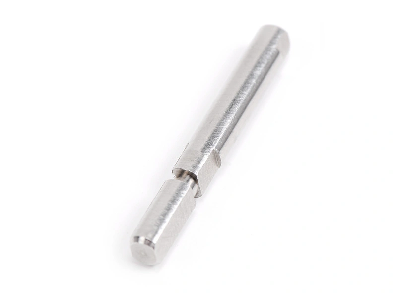
The Core Logic of High Volume Machining
The core logic is to increase output only after the process state and its evidence can be reproduced. Start with released authority and a route that represents planned production. Define CTQs, datums, material and finish states, tools, fixtures, inspection, sampling or monitoring, maintenance, containment, and lot disposition. Representative evidence should include the intended blank source, machine class, operator method, run duration, tool interventions, outside processes, and measurement state. A scale gate passes when those controls work together under representative demand, not when one first article conforms.
Consider an aluminum manifold family with locating holes, valve bores, intersecting passages, a sealing face, and an anodized final state. Fixture-pad contamination may shift bore position, drill wear may increase burrs, temperature may affect size, and anodizing may alter an interface. A representative pilot should expose these mechanisms. Because the final finish can change dimensions or hide surface evidence, pre-finish measurements cannot automatically release the finished interface. The pilot should verify seating, tool and offset rules, burr control, final-state measurement, finish-lot traceability, containment, and restart evidence before output increases.
Production Focus | Prototype Logic | High Volume Logic | Buyer Benefit |
|---|---|---|---|
Main objective | Answer a defined design, fit, or test question | Release accepted parts through a controlled and repeatable route | Separates design learning from production authorization |
Fixturing | Flexible restraint may suit a limited learning build | Released datums, seating, clamp effects, wear, and maintenance are controlled | Reduces setup-dependent feature movement and restart uncertainty |
Inspection | High coverage can describe a small sample | Risk-based measurement, monitoring, escalation, and lot disposition are defined | Provides release evidence without treating inspection as process stability |
Tool strategy | Tools may only need to complete the test quantity | Identity, use window, intervention authority, change verification, and trace are controlled | Connects wear mechanisms to CTQs and affected output |
Cost logic | Learning speed can outweigh recurring efficiency | Cycle, yield, material, inspection, tooling, and overhead are compared per accepted part | Prevents a lower quoted cycle from hiding scrap or control cost |
Fixtures, SPC, and Tool Life Management Drive Consistency
Fixture Strategy
Fixture strategy maintains consistency by reproducing the released datum simulation and restraint without unacceptable seating error or part distortion. A production fixture needs defined locators, supports, clamp sequence and force, cleanliness checks, load confirmation, wear limits, maintenance, and restart verification. Increasing cavities or combining operations is useful only when access, chip evacuation, probing, free-state results, and CTQ relationships remain valid. Verification should repeat after locator replacement, repair, relocation, crash, program change, or another event that can alter the setup state.
The same fixture principle applies across automotive and consumer products, but the acceptance risks differ. A fluid connector may prioritize sealing and thread relationships, while a visible enclosure may combine assembly datums with cosmetic zones. The fixture plan should follow the drawing and final condition rather than an industry label. Buyers should request locator logic, clamp-risk evidence, cleaning and maintenance criteria, first-off rules after intervention, and the method used to detect a misloaded or incompletely seated part.
SPC for Batch Control
SPC supports batch control when a selected characteristic, sequential data, subgroup logic, measurement system, control limits, and reaction rules are valid for the process. Specification limits define acceptance; control limits describe observed process behavior. A point inside specification can still signal abnormal movement, while a stable chart does not make an incapable process acceptable. Measurement resolution, uncertainty, datum simulation, part temperature, and operator method must suit the claimed signal. The chart must be tied to a CTQ, plausible cause, and authorized response.
For the manifold example, an upward valve-bore trend may relate to tool wear, temperature, or offset handling. The chart does not identify the cause by itself. The reaction should verify measurement, contain the correct lot boundary, check tool and fixture state, correct the confirmed mechanism, and document restart evidence. Sampling frequency should follow risk, process history, contract requirements, and escape consequences. Automatic offset correction without diagnosis can hide fixture movement or measurement error and shift another related feature.
Tool Life Management
Tool-life management controls the period in which a tool can produce its assigned features under the released process conditions. Wear can change size, cutting force, heat, burr formation, texture, and breakage risk. The plan should identify the tool, operation, monitored signal, use window, check frequency, offset authority, replacement trigger, and verification after change. Changes in blank hardness, coating, coolant, engagement, or chip evacuation may invalidate the original window. A preset interval is a maintained process limit, not permanent proof of identical tool behavior.
Replacing tools too late can increase scrap, containment, and rework; replacing them without evidence can add unnecessary cost and interruptions. Representative data should establish the initial window, while continued production evidence should confirm or revise it. The monitored feature must actually respond to the relevant wear mechanism, or the check can provide false confidence. Tool changes also need traceability to the affected lots. If a tool breaks or a signal exceeds its rule, the response must define last-known-good output, inspection scope, disposition, and restart authority.
Control Method | Main Function | What It Protects | What Happens if Weak |
|---|---|---|---|
Dedicated fixtures | Reproduce datum location, support, restraint, and access | Position, orientation, free-state geometry, and setup release | Seating shifts, distortion, correlated errors, or uncertain restart |
SPC monitoring | Detect defined non-random process movement | Selected CTQs under stated data and measurement conditions | Drift may continue until acceptance failure or final inspection |
Tool-life management | Control wear, intervention, replacement, and change verification | Size, burrs, surface condition, tool integrity, and affected-lot trace | Unplanned offsets, breakage, rework, scrap, or excess tool cost |
In-process gauging | Provide a suitable signal at the planned process stage | Timely reaction when method, uncertainty, and datum simulation fit | False correction or missed error if the signal is not suitable |
How Unit Cost Drops as the Process Stabilizes
Unit cost drops when the accepted-part cost tree improves, not merely when scheduled quantity rises. The cost basis should separate setup allocation, cutting and handling, tools, fixtures, material, outside processing, inspection, downtime, rework, scrap, packaging, and support. Stable production can spread fixed work, reduce repeated intervention, and improve yield. Purchased-part economics should also include freight, inventory exposure, supplier minimums, rejected-lot recovery, and any buyer-side sorting or assembly disruption. Those benefits need comparable evidence under the same drawing, route, lot, final state, and acceptance method.
A faster cycle can raise real cost if heat, chip accumulation, tool wear, clamp distortion, or inspection escalation increases. Likewise, reduced inspection is not a saving unless contractual requirements, characteristic risk, measurement suitability, process history, escalation, and lot disposition support the change. The comparison should divide total controlled production cost by accepted output under the agreed basis, rather than by gross machine quantity. Buyers should request before-and-after cycle, yield, CTQ, tool, downtime, and inspection evidence. Tooling and validation investments should be separated from recurring accepted-part economics.
Cost Factor | Early Production Stage | Stable Volume Stage | Reason Unit Cost Falls |
|---|---|---|---|
Programming and setup | Route, offsets, work instructions, and release gates are being verified | Released work is reused under controlled revision and changeover | Approved fixed effort is allocated across accepted output |
Cycle time | Representative limits and intervention needs remain under study | Cutting, loading, probing, tool changes, and recovery are controlled | Repeat work is removed without weakening CTQ control |
Inspection burden | Evidence is collected to understand risk and process behavior | Risk-based monitoring, sampling, escalation, and release are established | Measurement effort follows risk rather than unresolved uncertainty |
Scrap and rework | Failure modes, lot boundaries, and reactions are still being closed | Verified causes are controlled earlier with defined containment | More purchased input reaches accepted final-part status |
Tool usage | Initial windows may be conservative or unsupported by long-run data | Use limits and interventions follow maintained feature evidence | Avoids both wear-related loss and unsupported early replacement |
When to Move from Prototype to Mass Production
Move from prototype to mass production only when design authority, committed demand, material and finish, CTQs, production route, measurement, yield, capacity, supply-chain timing, and reaction rules are sufficiently mature for release. A prototype pass or calendar target is not a release gate. Capacity evidence should identify the real bottleneck, including machining, inspection, outside processing, cleaning, packaging, material supply, and recovery after interruption. If revisions, concessions, route assumptions, or acceptance methods remain open, low-volume manufacturing can preserve flexibility while representative evidence is completed.
The release pilot should use the planned material source and condition, production fixtures, tools, program, outside processes, inspection, packaging, and lot records. It should exercise first-off, tool change, planned maintenance, interruption recovery, and nonconformance response where relevant. Design, manufacturing, quality, purchasing, and the supplier should review one evidence package instead of approving separate assumptions. The decision records what passed, what remains limited, who owns changes, and which events require revalidation. Forecast volume matters only after technical and commercial authority agree.
Transition Condition | Why It Matters | Mass Production Readiness Signal |
|---|---|---|
Drawing frozen | Fixtures, programs, inspection, tooling, and records need one released authority | Revision owner, deviation status, and change process are documented |
Prototype validated | Design evidence must answer its intended fit, function, and test questions | Results and concessions are closed without claiming production capability |
Demand forecast available | Tooling, material, capacity, and supplier commitments need commercial authority | Committed and forecast quantities, timing, flexibility, and liability are separated |
Critical dimensions defined | Control plans require CTQs, datums, methods, frequency, and reactions | Final-state acceptance and measurement suitability are approved |
Material and finish confirmed | Grade, condition, blanks, heat treatment, and coating can change results | Representative route and outside-process controls have release evidence |
Which Components Fit High Volume Production Machining Best
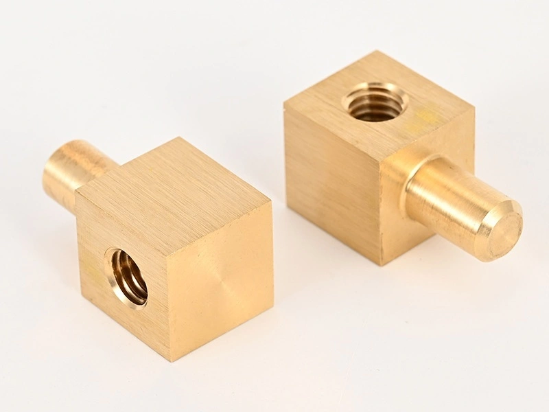
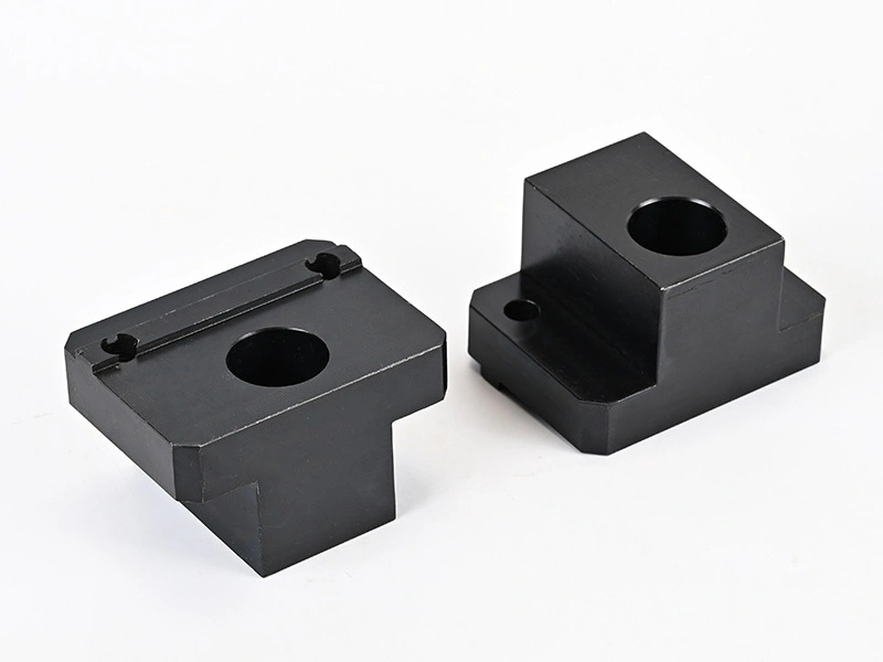
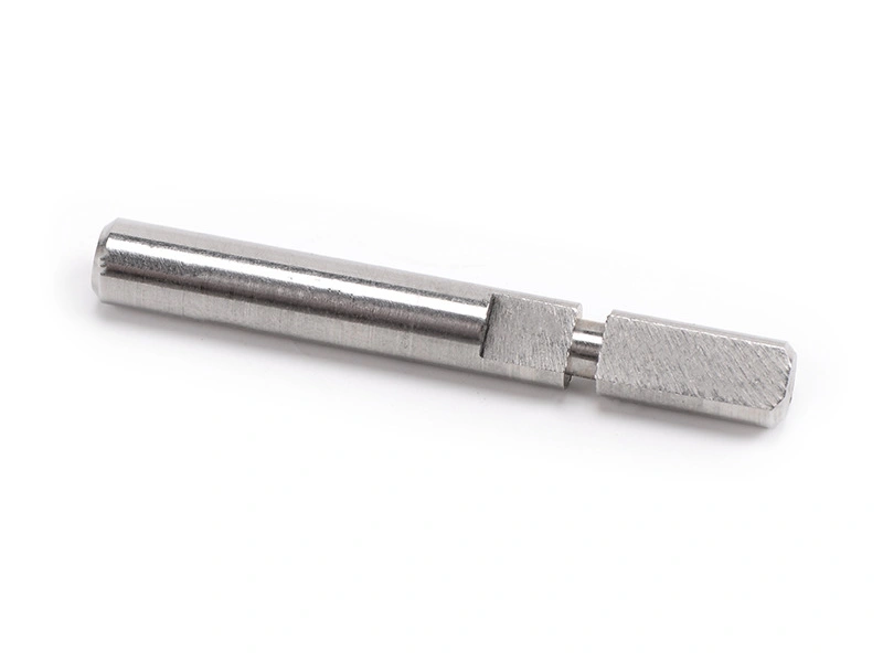
Components fit high volume production machining when repeat demand can justify production engineering and the accepted part still depends on efficiently machined CTQs. Suitable parts often include shafts, valve bodies, manifolds, connectors, mounting blocks, inserts, brackets, and precision housings. The exact material grade, temper, heat treatment, stock form, and finish can change tool behavior, restraint, allowance, and inspection. The geometry should provide usable datums, stable restraint, tool access, chip clearance, manageable stock removal, and practical final-state inspection. Part names alone do not establish suitability.
Applications in automotive and consumer products can qualify when their specific drawings, materials, approvals, and finish controls support the route. Thin shells, high stock-to-finished ratios, or shapes dominated by near-net geometry may favor casting, forging, molding, stamping, or extrusion followed by selective CNC. A hybrid-route pilot should verify blank variation, machining allowance, datum creation, flash or gate location, secondary CTQs, tool access, and final yield. Buyers should compare pure CNC and credible hybrid routes using tooling, revision exposure, yield, secondary operations, CTQs, and total accepted-part cost.
How Buyers Reduce Unit Cost Without Losing Precision
Buyers reduce unit cost without losing precision by finding the dominant cost mechanism and changing only what does not weaken released CTQs. Possible actions include improving fixture loading, combining operations, controlling tool intervention, selecting qualified stock or near-net blanks, removing nonfunctional geometry through design authority, and aligning inspection with risk. Changes to material source, blank route, fixture, program, tool strategy, measurement, finish, or packaging need an impact review and appropriate revalidation. Each action needs a representative trial, comparable cost basis, affected-feature review, approval gate, and reversion condition.
The RFQ should state drawing revision, demand ranges and commitment, material grade and condition, CTQs, datums, final finish, cosmetic zones, cleanliness, inspection, records, lot definition, packaging, outside processes, and change authority. Ask the supplier to identify assumptions, fixture and tool strategy, measurement methods, scale gates, capacity basis, yield disposition, cost breakpoints, and restart rules. The supplier workflow should connect machining to deburring, cleaning, finishing, final inspection, preservation, and packaging because a saving in one operation can create loss downstream. This evidence supports a buyer decision without turning a machine claim into a part guarantee.
Conclusion
High volume production machining scales precision parts by connecting released authority, representative routes, fixtures, tool-life control, suitable measurement, process signals, traceability, containment, and lot disposition. Consistency comes from controlling the mechanisms that move each CTQ and reacting before affected output is released. The control boundary also includes material, deburring, outside processing, cleaning, handling, and final-state inspection. Lower cost follows when verified setup, cycle, yield, material, inspection, tooling, and support improvements reduce accepted-part cost without changing the approved functional result.
A project is ready for the mass production route when technical release and committed demand support the same controlled plan. Until then, the low-volume manufacturing stage should close route, validation, and commercial assumptions. Before sustained output, buyers should approve scale gates, evidence, limits, lot definition, change ownership, deviation handling, and revalidation triggers. That decision is stronger than relying on a conforming sample, a machine list, or an unsupported capacity statement. The approved basis also defines what evidence is required after future production changes.
FAQ
What Is High Volume Production Machining and How Does It Differ from Prototype Manufacturing?
When Should a Project Move from Prototype Parts to High Volume CNC Production?
How Is Consistency Maintained Across Thousands of High Volume Machined Parts?
Which Types of Components Are Best Suited for High Volume Production Machining?
How Can Buyers Reduce Unit Cost in High Volume Machining Without Losing Precision?