CNC Powder Coating: Masking, Thickness, and Final-Part Acceptance
CNC Powder Coating: Masking, Thickness, and Final-Part Acceptance
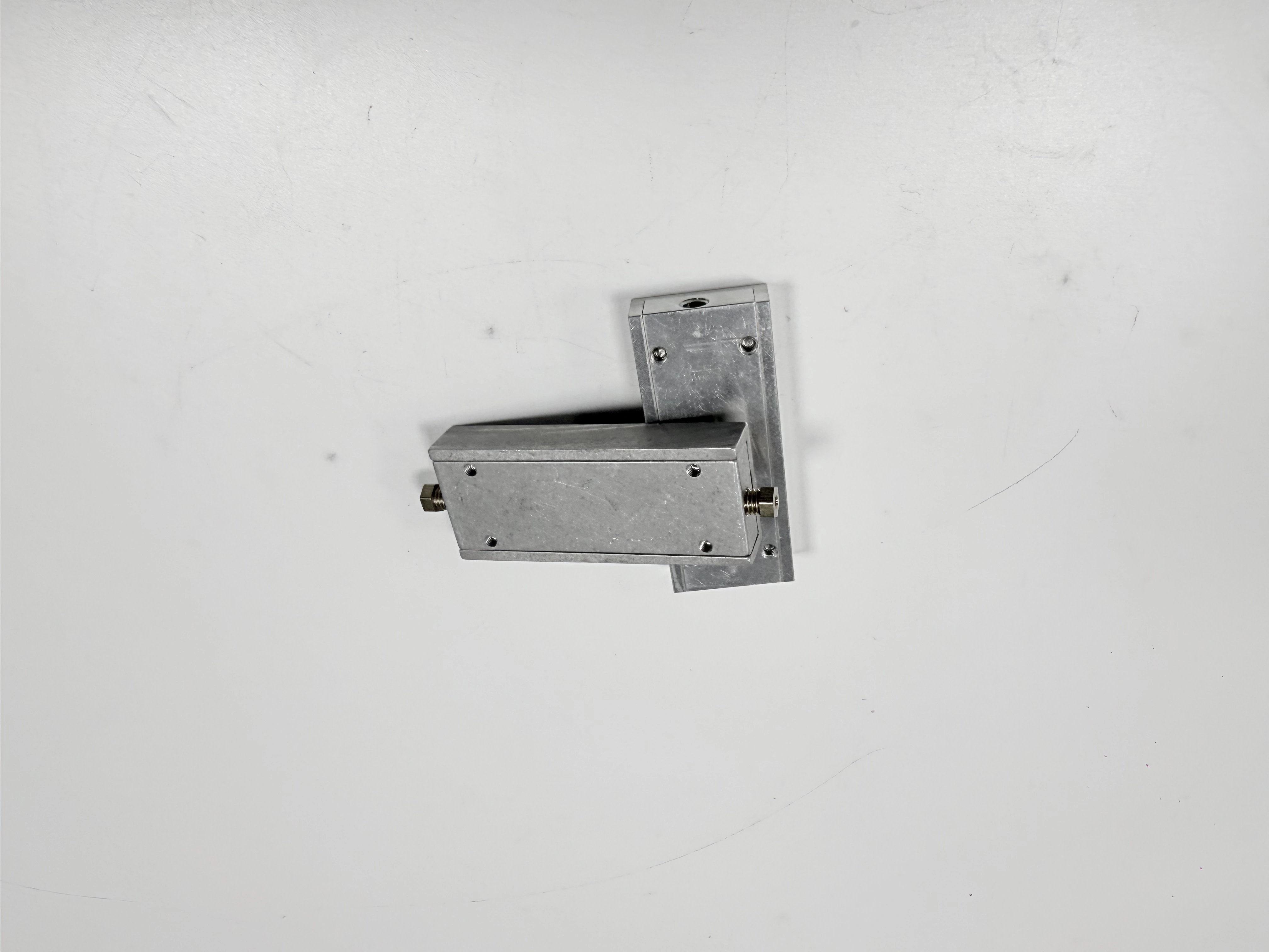
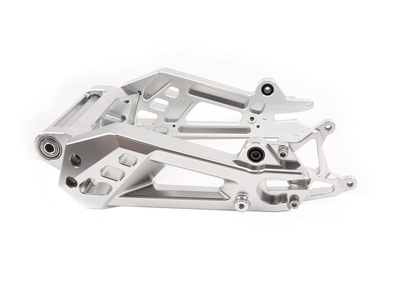
CNC powder coating is a controlled finishing route in which a prepared machined part receives a charged powder layer and a defined cure cycle; it is not simply a white or colored appearance. Buyers should decide which faces, bores, threads, datums, edges, and labels must remain usable, then define preparation, masking, film-thickness evidence, cure evidence, inspection state, and packaging. The pictured bracket shows a light-colored surface and a recognizable bent profile from two views. Those views support only visible geometry and appearance; they cannot prove powder chemistry, coating thickness, adhesion, corrosion performance, cure temperature, or material. A metal-finishing reference can organize the process discussion, while the drawing and acceptance plan control the delivered part.
Define the Coating Decision Before Quoting
Start by stating why powder coating is being considered. The objective may be a specified color, a protected exterior, electrical isolation, a cleanable surface, or a controlled visual finish. Each objective creates different evidence and limits. A color request alone does not define film thickness, adhesion, masking, edge coverage, gloss, texture, or resistance to the buyer's environment. Write the service state as machined, deburred, cleaned, coated, cured, inspected, and packed so every supplier is pricing the same handoff.
Map the part into functional and nonfunctional regions. Mark locating datums, threaded holes, press fits, bores, sealing lands, sliding surfaces, grounding points, drain paths, and cosmetic faces. State whether a region must remain bare, receive a reduced film, or accept coating with a post-coat allowance. A CNC machining reference may help identify the machined features, but it does not set the coating requirement.
Use the Bracket Views as a Scope Prompt
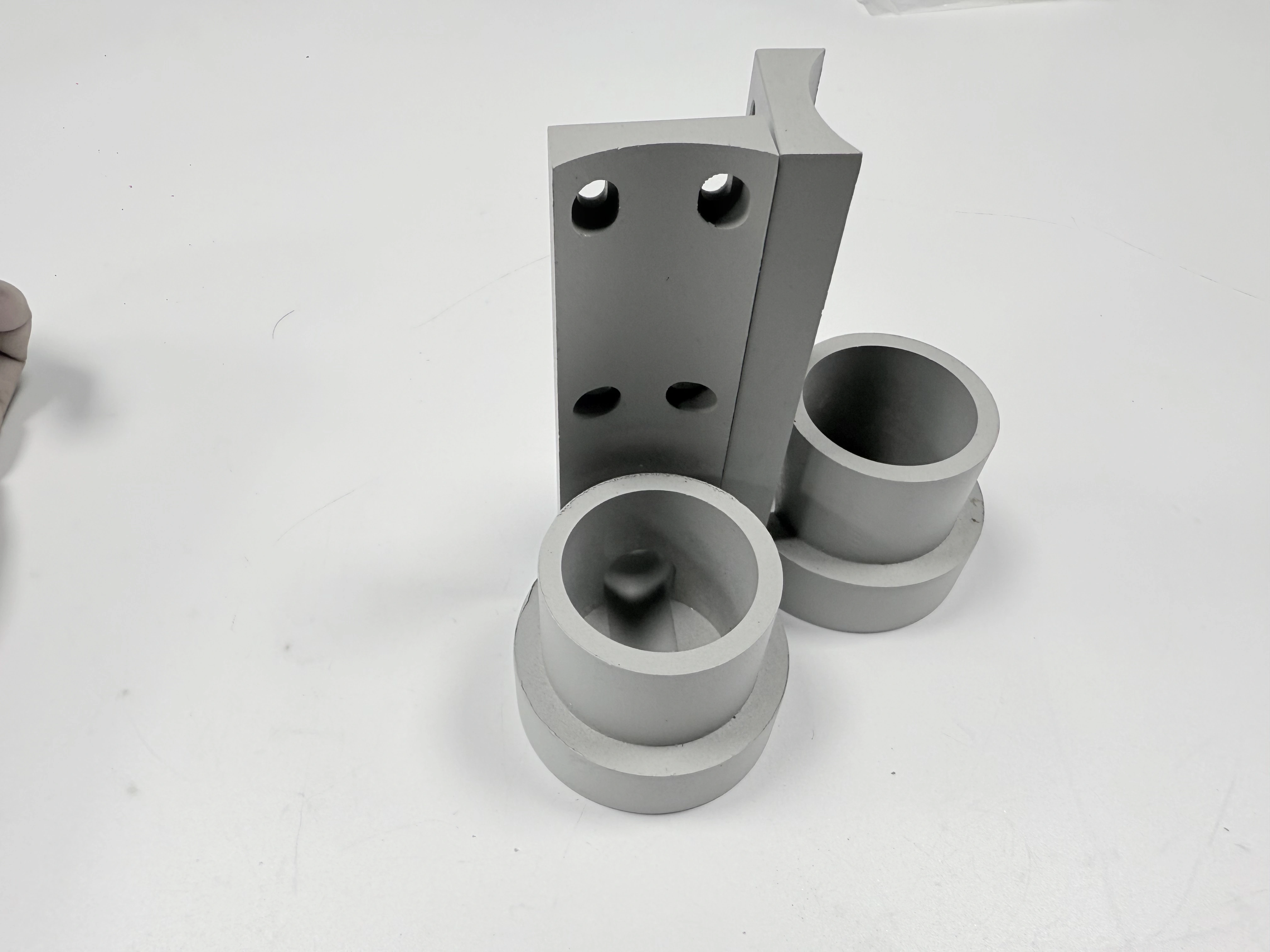
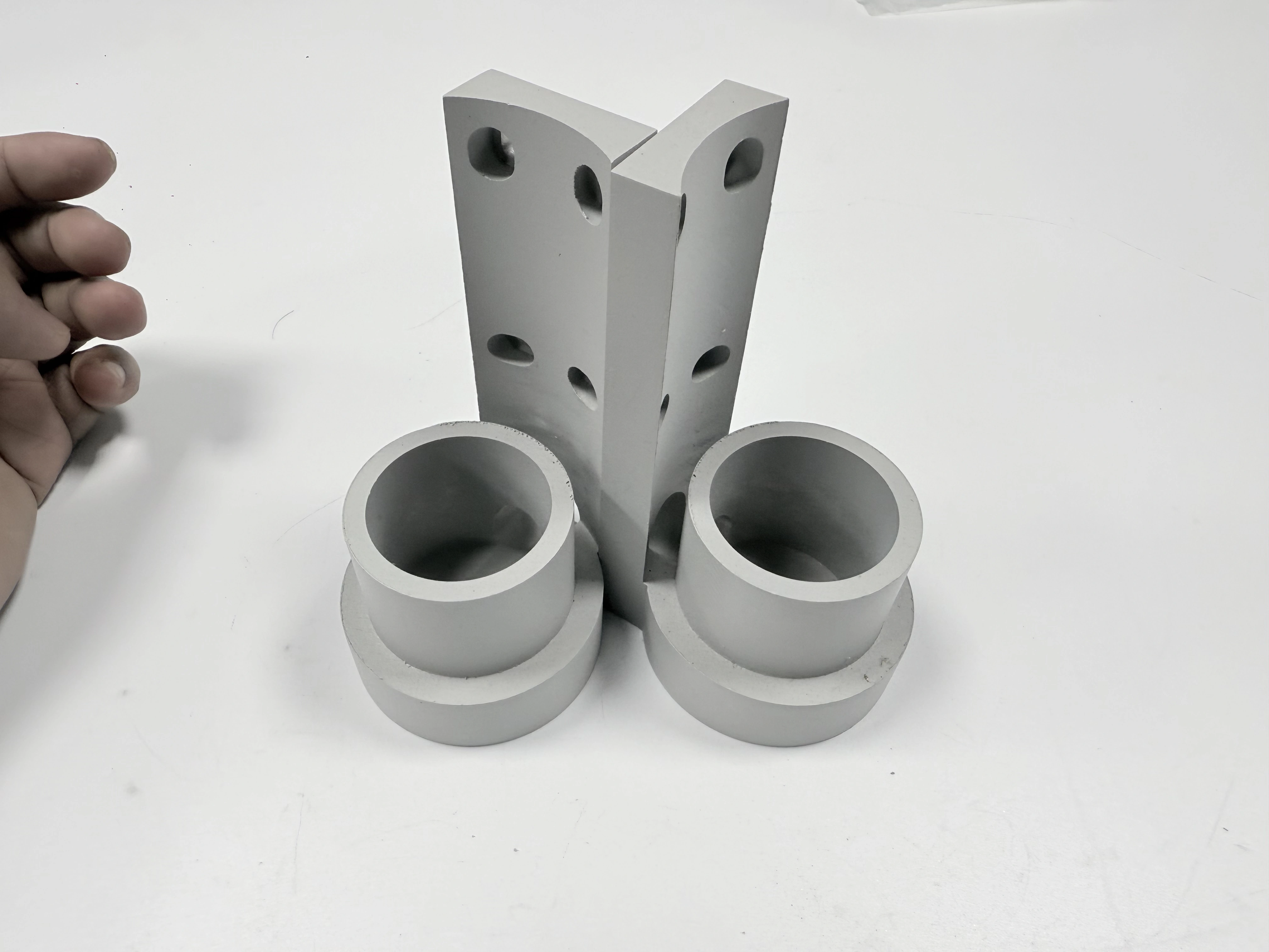
The paired images show one bent bracket with a light-colored visible surface, mounting features, and edges from different angles. They confirm a common physical product and a changed view. They do not reveal alloy, temper, pretreatment, powder type, film thickness, cure profile, adhesion, corrosion life, dimensions, or application. Use the views to ask where masking, rack contact, edge coverage, and inspection access are needed; use controlled documents for engineering conclusions.
Prepare the Machined Surface for Coating
Preparation determines whether the powder can wet, bond, and cure on the actual substrate. Define removal of chips, oil, coolant, fingerprints, loose oxide, and machining residue. State whether blasting, conversion treatment, chemical cleaning, or another approved preparation is allowed, and identify surfaces that could be altered by that route. Preparation that is suitable for a broad exterior may be unsuitable for a fine datum, a threaded hole, or a thin edge.
Record the substrate and its condition before preparation. Material designation, heat or lot, temper, hardness when specified, and prior treatment can influence cleaning response and dimensional change. Do not infer the material from the light color in the image. A material-selection reference can frame what the buyer should disclose; the certificate and drawing remain the evidence.
Control handling between machining and coating. A freshly deburred part can collect oil from gloves or gain corrosion products during storage. Define covered transfer, rack identification, maximum exposure, and the point at which a part must be re-cleaned. If a part returns from an outside processor, keep the processor batch and the receiving inspection connected to the unit or lot identity.
Choose Surface Profile Without Hiding Geometry
A preparation profile can improve mechanical keying, but it can also change a sharp edge, a small radius, or a fit. Specify the permitted profile or visual condition only where it matters, and state how it will be checked. A visual look after blasting does not prove a numeric profile, and a profile value from one flat region does not represent a narrow slot or a threaded feature. Record inaccessible regions and the alternate evidence used there.
Mask Threads, Datums, and Drain Paths Deliberately
Masking is a dimensional and functional decision, not just a cosmetic operation. Identify holes, bores, threads, datum pads, grounding points, sealing faces, and drain paths that must remain clear. Specify the masking boundary, permitted overspray, edge feather, and any cleanup that is allowed after cure. A turning reference can help describe turned threads and shoulders, while the drawing sets the actual keep-clear region.
Choose plugs, caps, tapes, liquid mask, fixtures, or another method according to geometry and temperature. A plug that seals a shallow hole may leave powder at a deep shoulder; tape may lift at an edge; a fixture can cover a contact surface but create a rack mark. State whether the mask is single-use, how it is identified, and how operators confirm removal before packing. A CNC fixturing guidance reference can frame support and access questions without replacing the mask map.
For a threaded or close-fit feature, define the inspection after masking and after cure. A gauge can reveal interference but does not prove that the coating boundary is located correctly. If a post-coat chase or hand cleanup is allowed, set the maximum removal and require a recheck of the thread, datum, or bore. Preserve the original coated condition when rework changes the evidence.
Plan Rack Contact and Edge Coverage
Every rack or hook contact creates an intentional uncoated or disturbed region. Mark where it may occur and whether it is hidden, functional, cosmetic, or electrically important. A contact point on a mounting datum can change seating; a contact point on a cosmetic edge can create a visible witness. Request a rack plan or a controlled contact sketch when the location affects acceptance, and identify how the part is oriented during spray and cure.
Edges receive powder differently from broad faces. A sharp outside corner can show thin coverage or a rounded powder edge, while an inside corner can collect extra film. State whether edge break, radius, or powder build is controlled and inspect the transition under defined lighting. Do not use a photograph to claim uniform coverage around every edge.
Control Film Thickness as a Stack-Up
Film thickness affects clearance, thread engagement, press fits, heat transfer, and visual texture. Define a nominal range or a drawing-specific allowance only when the coating specification and measurement method support it. A single reading on a broad face cannot prove the thickness inside a bore, at a corner, or near a mask edge. Map measurement zones and state which surfaces are excluded.
Specify gauge type, calibration, substrate response, number of readings, location, orientation, and acceptance rule. Preserve raw readings near a limit rather than reporting only an average. If a gauge cannot reach a recess or a thin wall, record the boundary and use a validated alternate method or a functional check. A quality inspection reference can organize the report fields but cannot establish the coating's specification.
Consider the dimensional stack before releasing a coated fit. Add coating allowance to the machined size only when the buyer has defined the coating state, both sides of the interface, and the measurement temperature. A hole masked before coating may remain clear, while an exposed bore can lose clearance. State whether dimensions are accepted before coating, after coating, after any approved cleanup, or at assembly.
Separate Coating Build From Machining Tolerance
Do not turn a coating thickness range into a machining tolerance promise. The machined feature, preparation, film build, cure shrinkage, and measurement uncertainty each have their own boundary. Review a worst-case stack for threads, bores, slots, and mating faces. If the stack cannot be closed with the chosen mask and film range, change the design or process through an approved revision rather than relying on hand fitting.
Match Powder and Cure to the Service Condition
Powder family, gloss, texture, color, substrate, and cure window should be specified from the environment and the functional surface. Outdoor exposure, cleaning chemicals, heat, abrasion, electrical contact, and appearance can require different choices. A color chip identifies appearance under its controlled lighting; it does not establish chemical resistance or service life. Record the approved powder product, batch, color code, gloss or texture reference, and any substitution rule.
Cure is a time-and-temperature condition in the part and coating system, not merely an oven setpoint. State the applicable cure requirement, part-temperature evidence, monitoring method, load configuration, and reaction to an interrupted cycle. A heat-treatment reference can distinguish thermal process documentation from coating cure evidence; it cannot certify this bracket's cure.
Consider thin and thick sections separately. A heavy corner may lag a thin flange, while a masked hole can cool differently from the exposed face. Record the representative location and the sensor or validation approach. If the part is sensitive to distortion or residual stress, define the dimensional checks before and after coating and identify the supporting fixture.
Keep Appearance Criteria Measurable
Define color reference, gloss or texture, lighting, viewing distance, angle, permitted variation, and inspector when appearance matters. A visual comparison should use an approved sample or instrument method at the same condition. Do not use a screen image or the two product photographs as a color standard. Record the reference revision when the buyer changes a chip, gloss level, or acceptable texture.
Recognize Coverage and Cure Failure Modes
Inspect for bare areas, pinholes, craters, runs, orange peel, trapped powder, thin edges, contamination, blistering, and rack witnesses according to the actual risk. Each defect needs a location, permitted extent, method, and reaction. A defect on a nonfunctional rear face may be handled differently from a defect at a seal, datum, grounding point, or threaded opening. Do not convert a generic “no defects” statement into an unbounded guarantee.
Look for signs that preparation, contamination, or cure is the cause, but do not diagnose from appearance alone. Adhesion evidence, solvent resistance, thickness readings, and cure records answer different questions. If a test is destructive, define the witness panel or sample and the relationship to production parts. Keep failed observations and the affected lot identity.
When touch-up is allowed, state the material, area, blend boundary, color match, and reinspection. Touch-up can change thickness, gloss, edge coverage, or corrosion protection. If it is not allowed, the reaction may be containment, strip and recoating, replacement, deviation, or a new trial. A deburring reference can help distinguish edge cleanup from coating rework; it does not authorize sanding away a coating.
Build a Characteristic-Specific Acceptance Plan
Map each characteristic to a method, state, sample, owner, and reaction: mask boundary, film thickness, color or gloss, edge coverage, rack contact, adhesion or cure evidence, critical dimensions, cleanliness, labels, and packaging. A visual inspection cannot prove thickness, and a thickness gauge cannot prove adhesion. Keep the evidence types separate but connect them to the same unit or sub-lot.
Define inspection timing. Some checks belong before coating, some after cure, and some at receiving or assembly. A masked thread may be checked after the mask is removed; a coated datum may require a post-cure CMM or fixture check. Record temperature, support, instrument, calibration, operator, and cleaning state when they influence the result. A CMM inspection reference can frame accessible location checks without proving the coating itself.
For a bracket with mounting features, verify the hole pattern, flatness or seating surfaces, edge condition, and any electrical or drain path separately. The image shows the outline but cannot prove these relationships. If a fixture or mating assembly is the functional test, define the fixture revision, force or torque condition, and acceptance response.
Choose Sampling From Risk and Change
Every-unit checks may be appropriate for a small lot when one blocked hole stops installation. Sampling can suit color or broad-face appearance after a stable process is established. A new powder batch, rack arrangement, masking method, oven load, preparation route, or outside processor creates a new state. Require a first-piece or expanded sample before treating that state as equivalent to the approved run.
Control the Handoff to the Coater
Provide the coater with drawing and model revisions, material identity, mask map, surface-preparation boundary, powder reference, cure requirement, film-thickness zones, appearance reference, inspection plan, packaging, and change authority. State what the coater may decide and what needs buyer approval. A CNC production planning reference can help align milestones, but it does not replace a part-specific handoff.
Ask the supplier to separate preparation, masking, powder, rack or fixture, cure monitoring, inspection, rework, packaging, freight, and engineering changes in the quote. Make quantity breaks and minimum charges visible. A low unit price may omit plugs, a witness panel, thickness readings, or protected packaging. Compare complete acceptance scope rather than a color name.
Require notice before changing powder product, batch, color, gloss, mask material, rack contact, oven, cure schedule, preparation chemistry, gauge, or packaging. Identify affected units and the first-piece evidence after the change. A parts-packaging reference can frame protection and labeling questions while the drawing controls the functional surfaces.
Keep a Traceable Coating Packet
Retain the active revision, material certificate, preparation record, powder batch, mask and rack identification, cure chart or validation, thickness readings, appearance reference, dimensional checks, rework history, packing identity, and approval. Link each record to a unit, serial range, lot, or defined sample. Preserve failed and replaced units rather than reporting only the final pass. A inspection reports reference can organize fields if its URL and scope are verified before publication.
Make Powder-Coating Scope Comparable in the RFQ
Provide controlled files, coating zones, mask boundaries, material and stock condition, machined dimensions, surface-preparation limits, powder reference, cure evidence, thickness method, appearance standard, inspection sample, rework rule, packaging, delivery condition, and change authority. Ask suppliers to list inclusions, exclusions, assumptions, and the evidence retained. Distinguish a coating-only quote from a complete machine-and-finish package.
State whether the order is prototype, qualification, production, second source, or repeat supply. Each purpose can justify a different witness panel, sample size, and record-retention period. Do not compare unlike purposes as though they carry the same risk. Request a redacted first-piece packet that shows the method, state, result, and disposition without requiring proprietary recipes.
Screen for Evidence and Reaction Capability
Compare suppliers on mask control, preparation discipline, powder and batch traceability, cure monitoring, thickness access, appearance references, rack planning, dimensional protection, rework control, packing, and change notification. A machine list or “powder coat included” phrase is not evidence. Prefer a response that names limits, owners, sample basis, reaction, and retained records.
Release the Coated Part With Explicit Boundaries
Release when the active revision, substrate, preparation state, mask map, powder and cure evidence, film-thickness zones, appearance criteria, critical dimensions, sample basis, delivered condition, and reaction rules agree. Hold when a thread or datum was not protected, a gauge cannot reach the required region, cure is inferred from oven temperature, a rack witness is undefined, or rework erased the original result.
The bracket images are a useful visual prompt, not a certificate. They show a shared product from two angles and a visible light-colored surface, while the drawing, coating records, measurements, functional checks, and receiving condition determine acceptance. Keep the release statement tied to the inspected surfaces, state, units, and method so a later order can be compared without expanding the original claim.
That boundary lets powder coating serve both appearance and function without pretending that color alone proves durability. The buyer's next action is to approve the mask, thickness, cure, inspection, and change-control map before production.
FAQ