
Car Parts Machining Guide: From Prototype Components to Production Parts
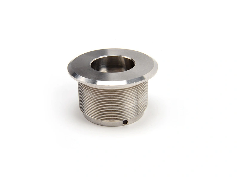
For vehicle programs, car parts machining uses CNC milling, turning, drilling, and related finishing to produce prototype and production components when the geometry, material condition, datum strategy, and acceptance evidence match the part's function. The route can support housings, shafts, cooling plates, brackets, sensor mounts, and sealing interfaces. A machined sample proves only the requirements that were actually represented and tested; it does not automatically prove that a later production process will repeat. Buyers should identify the build stage, critical features, production-intent differences, and release evidence before requesting a quote.
The practical task is to preserve design intent as the program moves from a testable component to a controlled recurring lot. Early parts may answer fit, access, thermal, sealing, or assembly questions. Pilot parts should expose variation from the intended blank, fixtures, tools, deburring, finishing, and inspection route. Production parts then need revision control, material traceability, defined acceptance, and a response to process drift. Effective CNC machining services connect those stages without treating one conforming prototype as evidence of stable production. The RFQ should therefore state what the part must demonstrate, not merely how many pieces are required.
What Car Parts Are Commonly Machined?
Commonly machined car parts include sealing and powertrain interfaces, rotational drivetrain features, EV cooling components, and mounting or structural hardware. The useful classification is functional risk, not the vehicle label alone. A housing can be governed by leakage, a sleeve by runout and wear, a cooling plate by flatness and cleanliness, and a bracket by hole-pattern location. Material, stock form, heat treatment, tool access, unclamped condition, finish, and measurement method determine whether CNC machining is suitable. The drawing and RFQ should connect each critical feature to its datum, failure mode, and acceptance check.
Engine-Related Parts
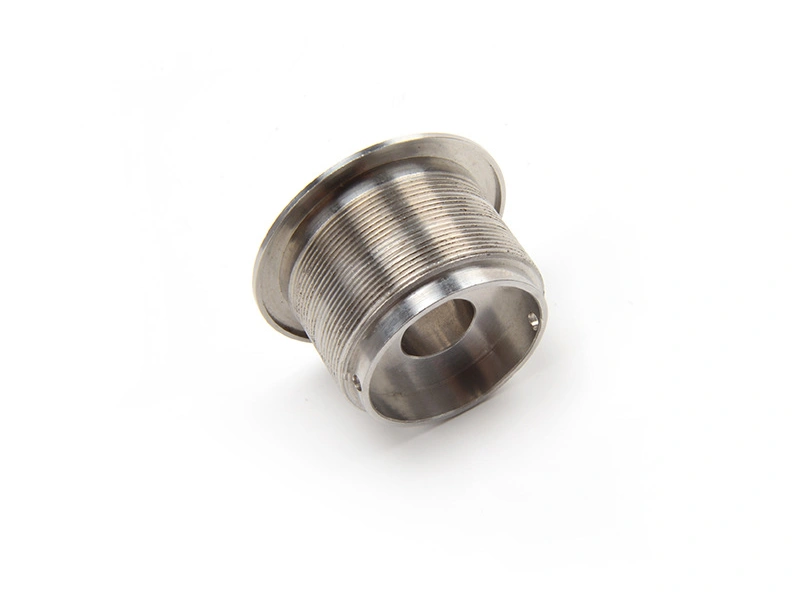
Engine-related machining covers housings, flanges, threaded connectors, sensor interfaces, shaft supports, and fluid-control features. The machining plan should protect relationships between bores, mounting faces, ports, threads, and sealing lands rather than chase isolated dimensions. A sealing face can meet size requirements yet leak because of waviness, scratches, burrs, or a surface texture that does not match the gasket or seal design. A bore can pass at one section while form or alignment prevents assembly. The supplier should define the setup datums, roughing and finishing sequence, deburring access, cleaning state, and post-process inspection. Buyers should specify the fluid, mating part, seal type, critical characteristics, material condition, and functional test when leakage or alignment controls release.
Transmission and Drivetrain Parts
Transmission and drivetrain parts commonly include shafts, sleeves, spacers, couplings, housings, and bearing or seal seats. Rotating function depends on the relationship among axes and shoulders, so diameter alone is not enough. Workholding error, center changes between operations, heat-treatment distortion, tool wear, or damage during handling can alter runout, roundness, surface texture, and shoulder location. The drawing should use the applicable GD&T controls and datum references for the intended assembly; ASME Y14.5 provides rules for stating and interpreting that design language. Inspection may combine dimensional measurement, runout checks, thread verification, and surface texture measurement. The RFQ should identify the mating components, load direction, final material state, finish state, and which characteristics require recorded results.
EV Thermal Parts
EV thermal machining includes cooling plates, manifold interfaces, electronics housings, channel covers, and mounting features that control coolant flow or thermal contact. The main risks are not limited to channel size. Thin floors can move after unclamping, sealing faces can distort during material removal or finishing, burrs can detach into a circuit, and trapped chips can compromise valves or pumps. A pressure test and a leak test are not interchangeable: the test medium, pressure or vacuum level, stabilization, allowable loss, duration, temperature, and fixture volume must follow the product requirement. Buyers should provide the coolant boundary, cleanliness criterion, sealed ports, flatness state, interface material, and test specification. The supplier should verify the final cleaned and finished condition, not infer sealing performance from machine inspection alone.
Mounting and Structural Parts
Mounting and structural parts include brackets, support plates, module carriers, sensor mounts, and housing interfaces. Their risk often lies in a hole pattern or contact plane that controls the location of another assembly. A bracket can measure correctly while clamped and spring after release, especially when walls are thin or stock stress is unbalanced. Edge condition also matters where wiring, hoses, hands, or adjacent parts pass nearby. The machining and inspection plan should define the free-state condition, datum sequence, thread acceptance, burr limit, and any functional checking fixture. Buyers should distinguish installation-critical holes from clearance holes, identify load paths and keep-out zones, and state whether coating thickness applies to mating faces or threads. This prevents blanket tolerances from adding cost without protecting assembly.
Car Part Category | Typical Function | Main Machining Priority | Common Risk if Poorly Machined |
|---|---|---|---|
Engine-related interfaces | Locate assemblies and retain air, oil, fuel, or coolant | Datum-related bores, sealing faces, ports, threads, and clean edges | Leakage or misalignment; confirm final-state dimensions, texture, and the specified functional test |
Transmission and drivetrain parts | Guide rotation, transmit load, and position bearings or seals | Axis relationships, form, shoulder location, surface texture, and final material state | Wear, noise, heat, or assembly failure; verify runout and mating features from declared datums |
EV thermal parts | Control coolant flow and maintain a thermal or sealing interface | Channel integrity, unclamped flatness, burr control, cleanliness, and sealed ports | Restricted flow, poor contact, or leakage; inspect after cleaning and finishing, then run the specified test |
Mounting and structural parts | Locate sensors, modules, housings, or adjacent subassemblies | Hole-pattern position, contact planes, threads, free-state shape, and edge condition | Forced assembly or datum shift; use drawing inspection and a functional check where fit drives release |
Prototype Car Parts vs Production Car Parts
Prototype car parts are built to answer defined design questions, while production car parts must come from a controlled route that can repeat the released definition. Quantity alone does not separate the stages. A one-piece sample can require production-grade traceability, and a larger test set can remain experimental if its material, blank, fixture, or finish differs from production intent. The buyer should record which differences are acceptable for the current test and which evidence must be repeated before pilot or production release. This keeps a successful fit check from being mistaken for process approval.
Prototype Design Priorities
Prototype design should maximize useful learning without hiding the conditions that limit the result. A part ordered through prototyping may validate installation space, fastener access, fluid routing, thermal contact, sealing, stiffness, or a particular load case. The exact alloy and temper matter when deflection, heat transfer, thread strength, wear, or corrosion is under review. Stock form matters when a future casting or forging will introduce different allowances, grain flow, porosity, residual stress, or locating features. The RFQ should identify the test objective, production-intent features, permitted deviations, drawing revision, material certificate scope, dimensional report, and functional test. A prototype can then be fast without becoming ambiguous evidence.
Production Design Priorities
Production design should freeze the interfaces that control function and make variation observable. The released drawing or model needs a coherent datum scheme, tolerances tied to assembly, finish and cleanliness requirements, and disposition rules for conflicting files. The manufacturing route should identify the blank, setups, fixtures, tools, deburring, heat treatment, coating, cleaning, and inspection state. First-off approval confirms the route started correctly; in-process checks detect drift; final inspection confirms lot acceptance. Tool wear can change bore size, texture, and burr formation before an operator sees a gross dimensional failure. Buyers should ask how those signals are controlled and what change requires requalification rather than accepting a generic claim of repeatability.
At higher or recurring volume, mass production decisions should be based on evidence from the intended process, not only on a prototype made by a different route. When the customer contract calls for AIAG Production Part Approval Process documentation, the submission level and required records should be agreed before quotation. PPAP is not an automatic requirement for every machined part. Regardless of the document name, the release package should show the approved revision, authorized material, process flow, critical controls, measurement method, dimensional or functional results, and disposition of deviations. A single conforming sample demonstrates that one part passed; it does not by itself establish capability across future lots.
Project Stage | Main Goal | Design Behavior | Cost Logic |
|---|---|---|---|
Prototype | Answer a named fit, function, thermal, sealing, or assembly question | Revisions and non-production-intent choices are allowed when clearly recorded | Pay for useful learning; release only the conclusions represented by the sample |
Pilot run | Expose variation and verify the intended blank, route, controls, and evidence package | Interfaces are stable; process differences and approved deviations remain visible | Invest in fixtures, first-off review, inspection, and corrective learning before recurring supply |
Production | Release conforming lots from a controlled configuration and repeatable process | Drawing, material, route, controls, and changes follow defined approval | Reduce total risk and unit effort without removing function-critical controls |
Surface Finishes for Functional and Visible Car Parts
Surface finishes for machined car parts should be selected by substrate, exposure, function, appearance, and the dimensions required after processing. Surface texture, coating thickness, corrosion treatment, and cosmetic color are different requirements. ISO 21920 defines how profile surface texture is indicated and evaluated; it does not replace a dimensional tolerance or a functional sealing test. A finish can change hole size, thread fit, edge radius, flatness, electrical contact, friction, and visual consistency. Buyers should mark functional, masked, cosmetic, sealing, grounding, and measurement areas on the drawing, then state whether acceptance applies before or after finishing.
Functional Surface Finishes
An as-machined surface can be appropriate when the specified texture, corrosion exposure, friction, cleanliness, and appearance are satisfied without an added process. For aluminum components, anodizing can provide an oxide layer, but alloy, anodize type, thickness, sealing, masking, and dimensional allowance must match the application. Stainless-steel passivation is a chemical treatment used to remove contaminants and support the material's passive surface; it is not a thick coating that repairs poor geometry. electropolishing removes material electrochemically and can alter edges or dimensions. The supplier should confirm stock allowance, masking, rack contact, post-process cleaning, and which features are remeasured in final condition.
Visible Surface Finishes
Visible automotive surfaces need an approved appearance boundary as well as a protective process. The drawing or cosmetic specification should define viewing zone, color or gloss reference, texture direction, acceptable handling marks, and whether adjoining parts must match. powder coating adds a comparatively thick polymer layer, so threads, precision bores, grounding pads, sealing faces, and tight interfaces may require masking or post-process work. Edge coverage and rack location can differ from broad flat surfaces. Buyers should approve a representative sample or controlled reference when appearance is subjective, then keep dimensional and cosmetic acceptance as separate records.
Finish Type | Best For | Main Benefit | Buyer Note |
|---|---|---|---|
As-machined | Controlled functional surfaces that need no added corrosion or cosmetic treatment | Avoids coating buildup and keeps the shortest qualified route | Specify texture, tool-mark limits, cleanliness, and final inspection state |
Anodizing | Compatible aluminum alloys requiring an oxide finish under a defined exposure | Provides a controlled surface layer and can support corrosion or wear objectives | Define type, thickness, sealing, color, masking, contact points, and dimensional allowance |
Passivation | Specified stainless-steel parts after machining and cleaning | Removes free-iron contamination and supports the passive surface condition | State the governing specification, alloy, cleaning condition, and required verification |
Electropolishing | Suitable metal surfaces needing controlled material removal and improved cleanability | Reduces microscopic peaks when the process is qualified for the geometry | Allow for dimensional change, edge rounding, fixturing contact, and final measurement |
Powder coating | Visible or protective areas with adequate coating clearance | Provides durable polymer coverage with controlled color and texture options | Mark cosmetic zones, masks, threads, grounding areas, sealing faces, and fit allowances |
Lead Time for Machined Car Parts
Lead time for machined car parts is the critical path through technical release, material, programming, workholding, machining, outside processing, inspection, approval, and transport. A prototype is not automatically faster than a pilot lot. An uncommon material condition, deep passages, thin walls, heat treatment, coating, cleaning, leak testing, or a detailed submission package can dominate the schedule even at low quantity. Production work may move predictably after fixtures and controls are qualified, but an engineering change can reopen programming and validation. Buyers should compare supplier dates only after confirming the same revision, quantity, finish, test, documentation, approval, and shipping scope.
A schedulable RFQ includes matching 2D and 3D revisions, material specification and condition, stock-form constraints, quantity by build stage, required-use date, finish, critical characteristics, test method, cleanliness, reports, packaging, and delivery destination. The supplier response should separate assumptions from committed milestones and identify approval holds. Useful gates include file release, material receipt, first-off review, outside-process return, final inspection, and shipment. Partial delivery can help only when the buyer defines which parts and records authorize use. An unsupported day count hides risk; a milestone schedule shows which decision or missing input can actually shorten the path.
How Buyers Should Source Car Parts Machining
Buyers should source car parts machining by matching supplier controls to the component's failure mode and build stage. A credible workflow begins with revision and requirement review, then confirms material and blank, manufacturability, datum transfer, setup sequence, tool access, deburring, finishing, cleaning, inspection, functional testing, and lot release. The supplier should identify conflicts between the model, drawing, specification, and intended use before cutting material. The quote should state production-intent differences, subcontracted processes, inspection assumptions, and records delivered. Supplier evaluation is stronger when it asks how a bore, sealing face, channel, thread, or hole pattern is controlled and verified, rather than asking for an unsupported universal tolerance.
Consider an EV cooling plate machined from production-intent aluminum stock. Roughing can redistribute residual stress; thin channel floors can move after unclamping; anodizing can affect masked and unmasked dimensions; incomplete deburring or cleaning can leave contamination in the coolant circuit. A defensible route references the mounting datums, sequences roughing and finishing, checks free-state flatness, controls channel edges, protects sealing areas, cleans the internal path, and applies the specified leak test after final processing. The RFQ should provide alloy and temper, stock form, mating geometry, coolant boundary, pressure or leak-test specification, cleanliness limit, finish and masks, critical dimensions, drawing revision, quantity by stage, and required evidence. The buyer can then decide whether the part proves fit only or is representative enough to support pilot release.
Conclusion
Car parts machining is ready to move from prototype to production only when the approved design, production-intent differences, material state, datum scheme, process route, finishing state, inspection, and functional evidence support the same release decision. Keep CNC machining when it provides the required geometry and the route can be controlled at the forecast volume. Revalidate when the blank, material condition, fixture, heat treatment, coating, test, or critical datum changes. Evaluate another manufacturing route when recurring volume, geometry, stock utilization, or required properties make machining an unsuitable production basis.
Use the existing automotive page to frame the vehicle application, then select prototyping for a defined learning build, mass production for a released recurring route, or broader CNC machining services when machining remains the appropriate process. Send one controlled RFQ package and ask the supplier to return assumptions, production-intent gaps, validation gates, and the evidence supplied with each lot. That response is more useful than a price or lead-time comparison built on different technical scopes.
FAQ
What Types of Car Parts Can Be Machined with CNC for Prototype and Production Use?
Is CNC Machining a Good Option for EV Car Parts Requiring Lightweight and Thermal Performance?
How Are Prototype Car Parts Different from Production Car Parts in Design and Cost?
What Surface Finishes Are Common for Machined Car Parts in Functional and Visible Areas?
How Quickly Can Machined Car Parts Be Delivered for Testing, Pilot Runs, or Production Support?
