
What Types of Car Parts Can Be Machined with CNC for Prototype and Production Use?
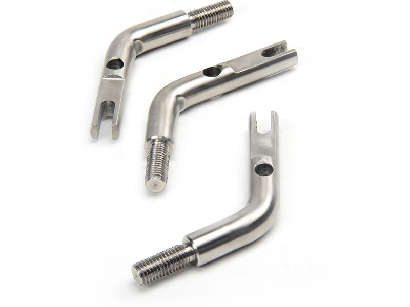
What Types of Car Parts Can Be Machined with CNC for Prototype and Production Use?
Powertrain shafts and housings, transmission carriers and valve bodies, cooling plates and manifolds, and brackets or sensor mounts can all be machined with CNC for prototype and production use. The part must have reachable features, a machinable material and blank, an economical route for the required quantity, and a way to inspect its functional interfaces. In the automotive supply chain, CNC may produce the complete part or finish critical features on a casting, forging, extrusion, or fabrication. Buyers requesting CNC machining should identify the project stage, material condition, production-intent blank, critical datums, final treatments, and required functional tests.
CNC serves a different purpose at each program stage. A billet prototype can answer geometry, assembly, motion, flow, or sealing questions without production tooling. A recurring part may remain fully machined when geometry and volume support that choice, but higher-volume parts often use near-net blanks with machined bores, threads, seal lands, and mounting datums. A prototype only supports the tests it represents. It does not prove casting porosity, forging response, production fixturing, tool-life stability, final coating effects, or sustained output.
1. Powertrain Parts Are Among the Most Common CNC Machined Automotive Components
Powertrain CNC candidates include shafts, sleeves, pump bodies, bearing carriers, housings, covers, and interface blocks. Shafts need controlled journals, shoulders, grooves, threads, and seal lands around a defined datum axis. Pump bodies and housings need located bores, port relationships, sealing faces, and clean internal intersections. The buyer should link each feature to its failure mode, such as poor bearing fit, excessive runout, leakage, misalignment, or restricted flow.
For rotational parts, CNC turning can establish diameters and axial relationships before grinding or other finishing where specified. Material condition still controls the route. Heat treatment, straightening, coating, or selective finishing can change size, form, texture, and datum relationships. Release evidence should therefore come from the specified final state and may include material records, hardness results, dimensional inspection, runout, fit, torque, or leak testing.
Automotive Part Area | CNC Role by Program Stage | Release Evidence |
|---|---|---|
Powertrain | Machine billet or bar prototypes; finish shafts, bores, seal lands, and faces on production blanks | Final-state size, form, runout, hardness, fit, torque, or leak results as applicable |
Transmission | Produce prototype shafts, carriers, or bodies; finish axis, bearing, hydraulic, and mounting features in production | Datum-aligned geometry, cleanliness, motion, pressure, leak, or flow evidence for the part function |
Thermal management | Machine prototype channels and ports; finish sealing, joining, and mounting interfaces on the released route | Final flatness, channel and cleanliness checks, pressure or leak test, and thermal validation |
Mounting systems | Machine complete development brackets or finish datum faces and holes on formed, cast, forged, or fabricated blanks | Hole position and datum results after coating plus assembly, stack-up, or calibration confirmation |
2. Transmission Parts Are Well Suited to CNC Because Fit and Axis Control Are Critical
Transmission parts suited to CNC include shafts, sleeves, bearing carriers, valve bodies, gearbox housings, covers, and precision spacers. Rotating parts depend on journal size, shoulder location, runout, and fits. Hydraulic bodies depend on bore and port relationships, sealing faces, burr control, and cleanliness. A machining plan should separate these acceptance needs because a dimensionally correct shaft can still fail through surface or runout error, while a clean-looking valve body can retain harmful burrs or chips.
Prototype transmission parts may be cut from billet to verify packaging, motion, hydraulic routing, or assembly. A production casting or forging introduces different locating surfaces, stock variation, porosity, distortion, and cleaning demands. The production release should use the intended blank, fixture logic, process sequence, washing method, and inspection plan. Rotating interfaces need datum-based geometry and fit evidence; hydraulic interfaces need final cleanliness plus the specified pressure, leak, or flow test.
3. Thermal Management Parts Are Increasingly Common in Both EV and Traditional Vehicle Programs
Cooling plates, coolant manifolds, ported housings, connector bodies, pump covers, and heat-transfer interfaces are practical CNC candidates for electric and conventional vehicles. CNC can locate open channels, threaded ports, sealing grooves, mounting holes, and flat contact surfaces. The functional risks are leakage, blocked flow, poor thermal contact, distortion, trapped chips, and coating or joining changes at the sealing boundary. The drawing and test specification should identify which of those risks controls release.
Not every thermal feature should be cut from one solid block. Inaccessible closed channels or material-efficient high-volume designs may require bonded plates, brazed assemblies, castings, extrusions, or additive routes, followed by CNC finishing. The final part must be checked after joining, heat exposure, cleaning, and surface treatment because those steps can change flatness, passage condition, or seal geometry. Pressure, leak, flow, cleanliness, and thermal tests should match the released design duty.
4. Mounting Parts and Sensor Supports Are Often Machined Because Position Accuracy Matters
Brackets, locator plates, sensor mounts, support blocks, and structural interfaces are machined when hole position, mounting faces, slots, threads, or datum relationships control assembly. The outer profile may be simple, but the functional stack can be sensitive to a small change at one interface. Prototype machining is useful for checking access and assembly. Production CNC may finish only the location-critical features on a formed, forged, cast, extruded, or fabricated blank.
The drawing should define functional datums and geometric controls under the selected interpretation, such as ASME Y14.5 or ISO 1101, instead of relying on ambiguous coordinate dimensions. Inspection should reproduce the intended datum setup. Coating thickness, masked surfaces, burrs, inserted hardware, and clamp distortion can change the final stack. Buyers should require final-finish hole and face results, then confirm assembly, sensor target position, or calibration where those functions are critical.
Part Type | Prototype Representation Limit | Production Route Evidence |
|---|---|---|
Shaft or sleeve | Billet or bar can prove fit and motion but not forging response, heat-treatment distortion, or normal tool drift | Production blank and treatment records with final journals, runout, texture, fit, and process-trend evidence |
Housing or cover | Billet can validate ports and assembly but not casting porosity, stock distribution, or production locating surfaces | Production-intent blank, fixture, washing, final geometry, cleanliness, and leak or functional results |
Cooling part | Machined channels can test flow and sealing but not the durability of a production joint or coating system | Released joining and finishing route with pressure, leak, cleanliness, flow, and thermal evidence |
Bracket or mount | A machined sample can prove geometry but not forming springback, weld distortion, coating buildup, or production handling | Production blank and coating with final hole, datum, stack-up, assembly, or calibration confirmation |
5. Prototype and Production Parts Are Often the Same Part Types but Used for Different Goals
The same car part may be machined in prototype and production, but the evidence is not interchangeable. Prototype CNC prioritizes learning while revisions remain open. Production CNC must repeat the released route under normal material, fixture, tool, special-process, measurement, and handling conditions. Buyers should state which question each prototype must answer and list every difference from production intent. That prevents a successful billet sample from being treated as proof of a future casting or forging process.
Consider a transmission valve body machined from billet to evaluate hydraulic passages, solenoid interfaces, fastener access, and assembly. Moving to a production casting changes stock allowance, porosity exposure, locating surfaces, distortion, deburring, and cleaning behavior. A useful pilot uses production-intent castings with the intended machining, washing, inspection, and pressure or flow test. The billet result remains valid for its declared tests, while production release depends on closing the new risks.
6. The Best CNC Candidates Usually Share the Same Feature Patterns
The strongest CNC candidates have reachable function-critical features and a material condition that can be cut, held, and inspected without unacceptable distortion. Typical signals include bearing or seal diameters, located bores, datum faces, threads, grooves, mounting patterns, ports, and controlled sealing or contact surfaces. CNC is also useful when revisions are likely or when low-to-medium demand does not justify dedicated tooling. The quote should still evaluate setup count, access, workholding, tool reach, deburring, final treatments, and inspection load.
Complete machining is a weaker choice for simple very-high-volume forms, thin sheet parts, deep inaccessible passages, or shapes that waste excessive stock. Stamping, forming, casting, forging, extrusion, fabrication, molding, bonding, brazing, or additive manufacturing may create the economical base form. CNC can then finish only the interfaces that need cutting accuracy. Buyers should compare the complete route, not the machining cycle alone, and verify the part after every step that can change critical geometry.
7. Why CNC Remains Important Across Both EV and Conventional Vehicle Platforms
EV and conventional vehicle programs both use CNC, but their dominant part risks can differ. EV applications often emphasize cooling manifolds, motor or electronics housings, battery-related interfaces, lightweight brackets, and sensor mounts. Conventional platforms commonly add engine, pump, transmission, shaft, and fluid-control components. Both groups need controlled datums, sealed or moving interfaces, burr management, material traceability, and final-state verification. The power source alone does not determine whether CNC is the right route.
The buyer should classify the component by function and failure mode before classifying it by vehicle platform. A cooling manifold is released through channel, cleanliness, sealing, and thermal evidence. A shaft is released through material condition, size, form, runout, texture, and fit. A sensor mount is released through datum-based position and assembly or calibration evidence. That part-specific logic produces a clearer supplier comparison than a generic EV or automotive capability claim.
8. Summary
Powertrain, transmission, thermal-management, mounting, and sensor-related car parts can be machined with CNC when their critical features are reachable and the selected material, blank, quantity, finishing route, and inspection plan support the function. CNC may make the whole prototype, remain the production route, bridge a tooling gap, or finish precision features on a near-net blank. Parts dominated by simple high-volume form or inaccessible geometry usually need another primary process.
An actionable RFQ for CNC machining identifies the drawing and CAD revision, project stage, quantity and forecast, material and condition, prototype and production-intent blanks, critical datums and features, heat treatment, finish, cleanliness, functional tests, submission needs, and approved changes. Specify CNC turning where rotational features drive the route. Release the next stage only when the part represents the intended process and its evidence closes the stated functional risks.



