Automotive Part Machining: Key Components, Materials, and Production Standards
In the automotive industry, machined parts are used wherever dimensional accuracy, reliable material performance, and controlled repeatability are required. These parts range from brackets, housings, shafts, and connectors to thermal management hardware, fixture details, sensor mounts, and transmission-related components. For buyers, automotive part machining is not only about making a part to drawing. It is about making parts that can move from prototype evaluation to controlled production while maintaining consistency, lead-time reliability, and commercial viability.
Automotive sourcing teams usually focus on three practical questions. First, which machining route best fits the part type and material? Second, how should the project move from prototype to pilot run and then into production? Third, can the supplier keep dimensional consistency and delivery performance stable as quantity grows? These questions matter because automotive parts often sit inside assemblies where even small changes in hole position, thread quality, flatness, or bore geometry can affect fit, vibration behavior, sealing, or long-term durability.
Common Types of Automotive Parts Produced by Machining
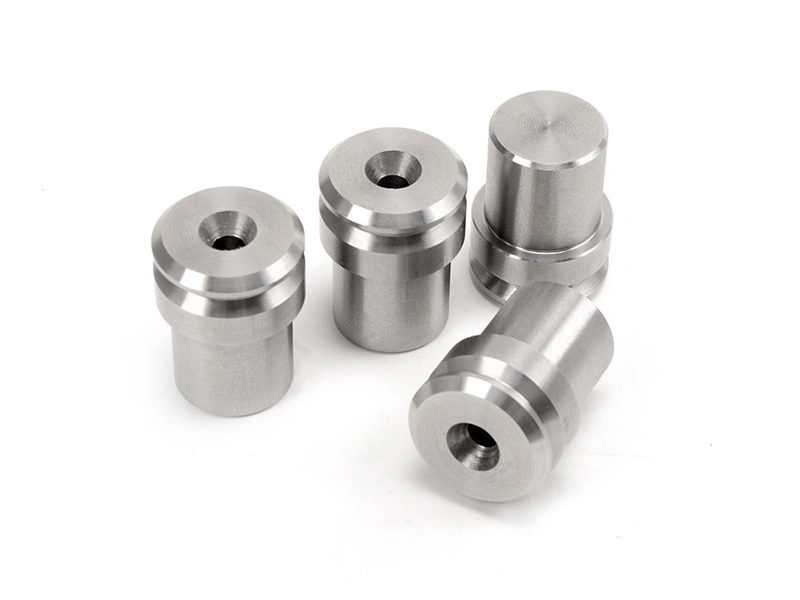
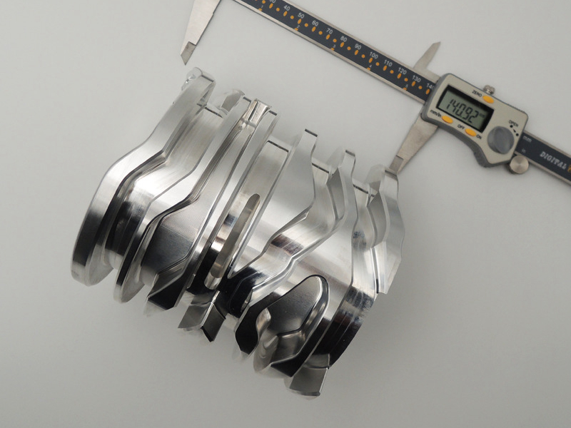
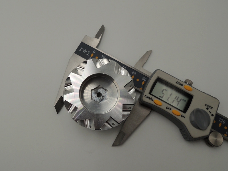
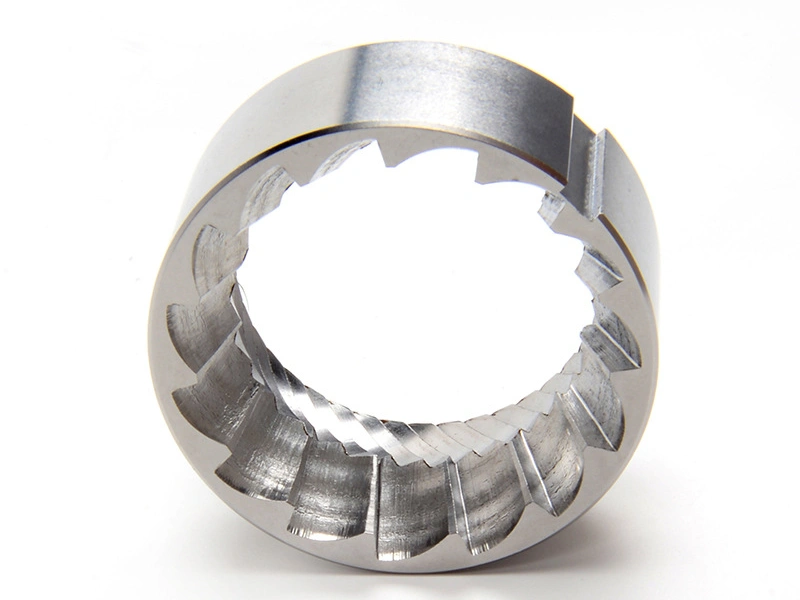
Automotive machining supports both structural and functional parts. Structural parts often include brackets, mounting frames, support blocks, and lightweight housings that must maintain stiffness and alignment. Functional parts may include shafts, sleeves, threaded adaptors, connector bodies, sealing interfaces, and heat-related components that depend on tighter control of size, geometry, and surface condition.
Some automotive parts are primarily prismatic and are best produced through CNC milling with additional drilling and tapping. Others are rotational and are better suited to turning, especially when concentricity, roundness, and thread quality are critical. The machining route should therefore match the geometry and function of the component rather than follow a one-process-fits-all approach.
Automotive Part Type | Typical Function | Main Machining Focus | Buyer Priority |
|---|---|---|---|
Brackets and supports | Mount components and control alignment | Flatness, hole position, thread quality | Stable assembly fit |
Housings and covers | Protect and locate internal systems | Pockets, bores, sealing faces, datums | Dimensional consistency and finish |
Shafts and sleeves | Support motion or rotational load | Diameter control, concentricity, surface finish | Wear behavior and repeatability |
Thermal management parts | Guide heat transfer or cooling flow | Channel geometry, flatness, wall stability | Functional accuracy and leak resistance |
Sensor and connection hardware | Provide accurate mounting and interface control | Threads, locating features, bore precision | Reliable integration into vehicle systems |
Material Selection for Automotive Part Machining
Material selection in automotive machining must balance weight, strength, corrosion resistance, machinability, and production cost. Buyers should select the material based on the real duty of the part instead of defaulting to the highest-performance alloy in every case. In most automotive programs, aluminum, carbon steel, and stainless steel each serve different roles.
Aluminum Applications
Aluminum CNC machining is widely used for lightweight automotive parts where weight reduction, thermal performance, and fast machining efficiency are important. Typical applications include housings, brackets, covers, mounting structures, and thermal management components. Aluminum is attractive because it offers strong machinability, lower density, and good compatibility with surface treatments such as anodizing.
Carbon Steel Applications
Carbon steel CNC machining is commonly used for automotive parts that need strength, durability, and cost-effective production. This includes shafts, supports, mechanical connectors, wear-related components, and structural details where higher load-bearing capability matters more than low weight. Carbon steel is often a strong choice when the part must remain robust under repeated mechanical stress and the environment does not require premium corrosion-resistant alloys.
Stainless Steel Applications
Stainless steel is used in automotive parts where corrosion resistance, cleaner surface quality, or long-term durability in exposed environments is especially important. It is often selected for fittings, fluid-related hardware, fastening interfaces, sensor-related structures, and components that must maintain integrity in wet or chemically exposed conditions. Although it is generally slower and more expensive to machine than aluminum, it provides strong performance where environmental durability matters.
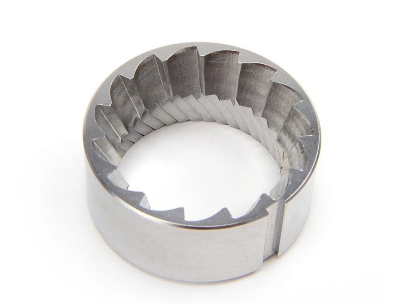
Material | Main Advantage | Common Automotive Use | Buyer Selection Logic |
|---|---|---|---|
Aluminum | Lightweight and easy to machine | Housings, brackets, thermal components | Best when weight and machining efficiency matter |
Carbon steel | Strength and cost efficiency | Shafts, supports, structural hardware | Best for durable functional components |
Stainless steel | Corrosion resistance and durability | Fittings, exposed hardware, fluid-related parts | Best for harsh or corrosion-sensitive conditions |
Prototype, Pilot Run, and Mass Production in Automotive Machining
Prototype Stage
In automotive development, prototypes are used to validate fit, function, geometry, and assembly logic before the part is released into broader supply. At this stage, the priority is usually engineering speed and learning. Buyers may use machined prototypes to confirm whether hole locations align correctly, whether thermal contact surfaces behave as expected, or whether the part integrates properly into a subsystem.
Pilot Run Stage
Pilot runs are used when the design is largely stable but the program still needs controlled pre-production supply. This stage is important for process validation, assembly trials, limited vehicle builds, and early field feedback. The supplier is no longer proving only that one part can be made correctly. They are proving that a short series can be made consistently, with stable dimensions and practical lead times.
Mass Production Stage
Once the design is frozen and demand is established, the project shifts toward mass production. At this point, buyers focus more on fixture stability, tool-life control, inspection discipline, and delivery reliability. The goal is lower unit cost without losing the dimensional and cosmetic consistency established earlier in development.
Production Stage | Main Goal | Supplier Focus | Buyer Concern |
|---|---|---|---|
Prototype | Validate design and assembly function | Fast response and machining flexibility | Engineering feedback speed |
Pilot run | Verify repeatability before scale-up | Short-batch consistency and process stability | Risk reduction before launch |
Mass production | Scale stable parts with predictable cost | Controlled fixtures, tools, and scheduling | Consistency and delivery performance |
Why Consistency and Lead Time Matter So Much in Automotive Programs
Automotive manufacturing depends on repeatability. A part that is correct in the first batch but drifts in the next can create assembly disruption, warranty exposure, and unexpected sorting cost. That is why automotive buyers place such strong emphasis on consistency. They want to know whether the supplier can keep hole locations, diameters, threads, sealing planes, and visible surfaces stable across recurring orders, not just during one successful build.
Lead time matters for the same reason. Automotive programs often run to structured milestones, pilot build schedules, and tightly coordinated production windows. Late delivery affects far more than the individual part. It can delay subassembly validation, line readiness, or vehicle release timing. Strong suppliers control lead time through material planning, setup discipline, repeatable fixturing, clear inspection flow, and realistic scheduling rather than optimistic quoting alone.
Production Standards and Quality Expectations in Automotive Machining
Automotive part machining is judged by more than nominal size. Buyers usually expect controlled dimensional repeatability, stable surface condition, clear process discipline, and the ability to support documented quality release where required. Features such as datums, bores, threads, sealing faces, and critical hole patterns often receive tighter attention because they directly affect vehicle assembly and component function.
Good automotive machining practice also means aligning inspection to part function. A shaft should be checked for diameter control and runout where those features matter. A bracket should be evaluated for hole position and flatness if it controls mounting alignment. A housing may require particular focus on bores, pockets, and sealing faces rather than only external dimensions. Buyers should therefore assess suppliers based on how well they understand critical features, not only on their general machining capacity.
Quality Focus Area | Why It Matters in Automotive Use | Typical Supplier Control Method |
|---|---|---|
Dimensional repeatability | Prevents fit and assembly variation | Stable process planning and inspection checkpoints |
Thread and hole quality | Supports fastening and subsystem integration | Tool monitoring, gauging, and controlled deburring |
Surface condition | Affects sealing, appearance, and wear behavior | Controlled finishing and visual review |
Batch consistency | Protects line stability and field reliability | Fixture discipline and repeat production controls |
Delivery reliability | Supports build schedules and launch timing | Material readiness and realistic production planning |
How Buyers Should Evaluate an Automotive Machining Supplier
When choosing a supplier for automotive part machining, buyers should look beyond initial price and ask whether the supplier can support the full program path. That includes prototype responsiveness, pilot-run consistency, production readiness, and the ability to work with the right materials for the part type. It also means checking whether the supplier understands which features are truly critical to assembly, durability, and surface function.
The best supplier fit usually comes from matching material capability, process discipline, and delivery performance to the actual needs of the program. A lightweight aluminum housing, a carbon steel support part, and a corrosion-sensitive stainless fitting may all belong to the same automotive project, but they do not require the same machining logic. Strong suppliers recognize that difference early and build the process around it.
Conclusion
Automotive part machining supports a wide range of precision components, from lightweight aluminum housings to durable carbon steel supports and corrosion-resistant stainless fittings. The best machining route depends on the geometry, material, and production stage of the part. Prototype work focuses on validation, pilot runs prove repeatability, and production programs demand stable output with dependable lead times.
If you are sourcing machined parts for vehicle systems or automotive equipment, the next step is to review the dedicated automotive industry page and compare it with the broader CNC machining services and mass production routes so material, process, and delivery strategy are aligned before ordering.
FAQ
What Automotive Parts Are Most Commonly Produced Through Precision CNC Machining?
Which Materials Are Best for Automotive Part Machining in Structural and Functional Applications?
How Does Automotive Part Machining Support Both Prototype Builds and Mass Production Programs?
What Tolerances and Surface Requirements Are Typical in Automotive Machined Components?
How Do Suppliers Control Quality and Repeatability in Automotive Part Machining?