
What Tolerances and Surface Requirements Are Typical in Automotive Machined Components?
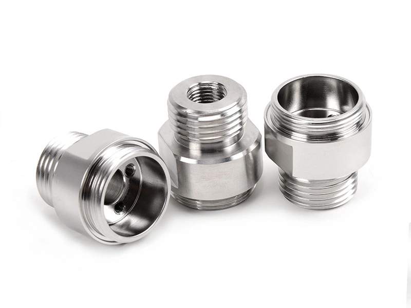
What Tolerances and Surface Requirements Are Typical in Automotive Machined Components?
Typical tolerances and surface requirements in automotive machined components depend on which features actually control fit, motion, sealing, vibration, or appearance. In most cases, the most important requirements are not applied equally across the whole part. Instead, engineers place tighter control on functional dimensions such as fit holes, bearing bores, shaft diameters, sealing faces, thread-related shoulders, and datum surfaces, while less critical outer areas are held to more practical limits. This is why good CNC machining for automotive parts is based on feature priority, not just overall dimensional tightness.
In real automotive production, consistency across the batch is often more important than achieving one extremely accurate sample. A housing, shaft, bracket, or sensor mount only creates value if the whole lot repeats the same functional geometry reliably. One perfect part and ninety unstable parts do not help a production line. That is why automotive machining focuses on tolerance stability, repeatable setups, and surface control on the areas that affect assembly and long-term performance.
1. Functional Dimensions Are Usually More Important Than General Outer Size
Automotive machined parts usually contain a mix of functional and non-functional features. Functional dimensions are the ones that determine how the part assembles or performs. These often include bearing seats, fit holes, locator faces, shaft diameters, groove widths, and mounting positions. Non-critical external geometry may still need to be controlled, but it usually does not deserve the same tolerance priority as the surfaces that carry load, locate another component, or support sealing and motion.
For example, a machined housing may depend on bore location and face flatness far more than on the outer wall profile. A shaft may depend mainly on diameter, roundness, and coaxial alignment. A bracket may depend on hole position and datum-face relationship more than on edge shape. This is why automotive tolerance planning should begin with function.
Feature Type | Typical Priority | Why It Matters |
|---|---|---|
Fit holes and bores | Very high | Control assembly accuracy, rotation, and alignment |
Shaft diameters and shoulders | Very high | Control fit, motion, and wear behavior |
Datum faces and mounting surfaces | High | Control location and repeat assembly |
Appearance surfaces | Medium | Influence cosmetic quality and customer perception |
General outer contour | Lower | Usually less critical than functional geometry |
2. Tolerance Stack-Up Is Often More Important Than One Single Dimension
Automotive assemblies are full of interacting parts, so engineers rarely judge a machined feature in isolation. What matters is how several dimensions combine across the assembly. This is why tolerance stack-up is such an important concept in automotive machining. A hole can be within its own limit, a locating face can also be within its own limit, and the assembled result can still shift if the combined variation is too large.
That is why good machining practice does not only hold dimensions individually. It also protects datum logic, positional relationships, and the few dimensions that truly control the assembly chain. In automotive parts, the ability to repeat these relationships from part to part is often more important than making one isolated feature exceptionally tight.
3. Fit Holes and Mating Bores Are Among the Most Critical Features
Fit holes and mating bores are common high-priority features in automotive machining because they often determine whether the component locates properly during assembly. These features may support bearings, dowels, shafts, bushings, sensor interfaces, or mating fasteners. If the bore size drifts, or if the hole position moves relative to the datum faces, the part may create misalignment, vibration, or uneven load transfer.
This is especially important in housings, support blocks, brackets, and rotating components. Automotive teams often pay special attention to these features because even a small variation can affect NVH behavior, bearing life, or assembly efficiency on the line.
4. Shaft-Type Parts Usually Depend on Turning Quality and Surface Stability
Automotive shafts, sleeves, and cylindrical connectors often rely heavily on CNC turning because turning controls diameters, shoulders, threads, and axis-related geometry efficiently. Typical tolerance priorities on these parts include diameter consistency, roundness, coaxial behavior, and shoulder location. These features directly affect bearing fit, seal life, and rotational smoothness.
Surface condition also matters strongly on shaft-type components. A diameter can measure correctly and still perform poorly if the surface finish is too rough or unstable. That is why shaft parts often combine tolerance control with strict surface expectations on journals, seal-contact areas, and precision shoulders.
5. Surface Requirements in Automotive Parts Are Usually Divided Between Functional and Appearance Surfaces
Not every surface on an automotive machined part needs the same finish. Functional surfaces usually need finish quality because they affect contact, sealing, motion, or wear. Appearance surfaces are different. They matter because the part may be visible to the customer or must present a clean consistent visual standard for the OEM or tier supplier. These two types of surfaces are often controlled differently.
For example, a bracket may have a visible face that needs a stable cosmetic finish, while its mounting holes and datum face require functional precision. A housing may use an as-machined finish on hidden interior features but require anodizing or powder coating on outer visible or corrosion-sensitive surfaces. In stainless applications, electropolishing may be selected when smoothness and corrosion performance both matter.
Surface Category | Typical Requirement | Example Automotive Part |
|---|---|---|
Functional bore or fit diameter | Stable finish for fit, wear, or sealing | Housing bore, shaft journal |
Datum face or mounting face | Controlled flatness and clean contact surface | Bracket base, sensor mount face |
Cosmetic visible face | Uniform appearance and finish consistency | Cover plate, visible housing surface |
Corrosion-sensitive exterior surface | Protective and appearance-oriented coating | Aluminum housing, exterior bracket |
6. Consistency Across the Batch Is Usually More Important Than One Perfect Part
In automotive machining, the line does not care whether one sample part is exceptional. What matters is whether every production part stays within the functional window and behaves the same way during assembly. This is why consistency often matters more than extreme one-piece accuracy. A slightly tighter first article does not create value if later parts drift enough to affect fit, appearance, or torque behavior.
That is also why automotive customers often evaluate a supplier by repeatability, not just by peak precision. Stable setups, controlled tool wear, and reliable inspection routines are often more valuable than chasing the smallest possible tolerance on non-critical features.
7. Typical Automotive Examples Show How Tolerance and Surface Priority Change by Part Type
A shaft usually places the highest priority on diameters, roundness, shoulders, and contact surface finish. A housing usually prioritizes bores, face flatness, hole location, and sealing or fit features. A bracket usually prioritizes datum faces and hole position. A sensor mount usually depends on interface location and stable mounting geometry. These examples show that “typical automotive tolerance” is not one universal number. It is a feature-based decision tied to how the part works.
This is why the best machining plans identify which surfaces are functional, which are visible, and which are secondary. That approach helps control cost while still protecting the features that really matter in the vehicle system.
8. Summary
In summary, typical tolerances and surface requirements in automotive machined components are built around functional dimensions, tolerance stack-up, fit holes, datum faces, and the difference between working surfaces and appearance surfaces. Parts such as shafts, housings, brackets, and sensor mounts all have different priority features, but the common rule is the same: the features that control assembly and function deserve the most attention.
The most important lesson is that consistency usually matters more than one-piece perfection. In automotive production, a supplier creates value by repeating the same functional geometry and surface quality across the lot, not by making one outstanding sample. That is why strong CNC machining, precise turning, and the right finish choice such as as-machined, anodizing, powder coating, or electropolishing are all part of delivering reliable automotive components.



