How are tolerances and deformation controlled in superalloy CNC machining?
How are tolerances and deformation controlled in superalloy CNC machining?
Superalloy machining tolerances and deformation are controlled through early DFM review, stable fixturing, balanced material removal, staged roughing and finishing, stress-relief planning when needed, heat treatment control, tool wear monitoring, and final verification after critical operations. From an engineering perspective, tight-tolerance superalloy machining is not controlled by one single step. It depends on a full process route designed to manage heat, stress release, and dimensional drift in superalloy machining tolerances projects.
Control Method | Why It Matters |
|---|---|
DFM review | Identifies thin walls, deep cavities, over-tight tolerances, and clamping risks before production |
Stable fixturing | Reduces vibration, distortion, and repeat positioning error |
Balanced material removal | Helps prevent one-sided stress release and part movement |
Roughing and finishing separation | Allows stress to release before final dimensions are completed |
Stress relief planning | Reduces the risk of later deformation during machining or service |
Heat treatment planning | Accounts for dimensional change after thermal processing |
Tool wear monitoring | Prevents size drift caused by edge degradation |
CMM inspection | Confirms critical dimensions and geometric tolerances after key steps |
1. DFM review is the first step in controlling superalloy distortion
Deformation control starts before machining begins. A proper DFM for CNC machining review should identify thin walls, long slots, deep pockets, unsupported sections, and unrealistic tolerance zones. These features are more sensitive in superalloys because the material retains strength, stores stress, and reacts less forgivingly than standard metals.
2. Fixturing must control the part without over-constraining it
Stable fixturing is critical in precision Inconel and other superalloy parts because excessive clamping force can create distortion, while weak support allows vibration and dimensional instability. The fixture strategy should hold the datum structure repeatably and support the part through the highest-risk operations, especially on complex components that may also require multi-axis machining.
3. Balanced stock removal reduces stress-release problems
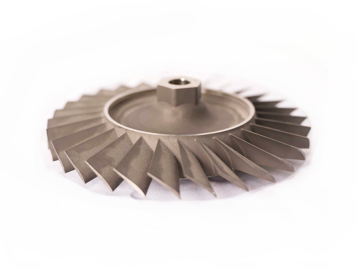
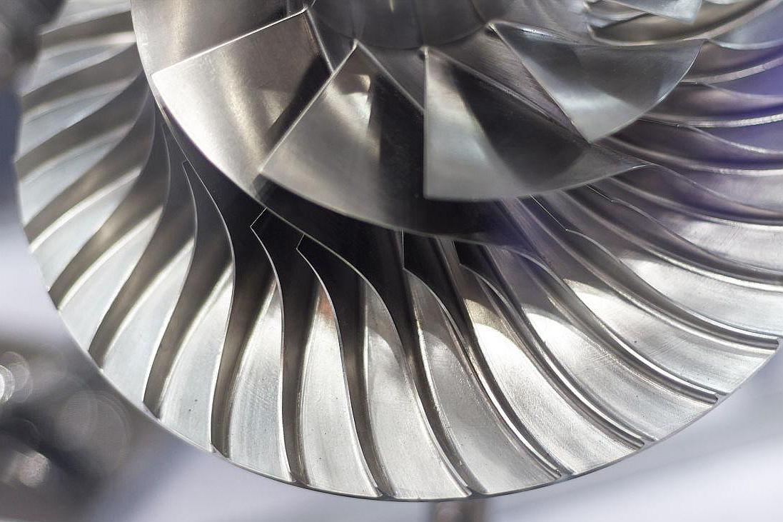
Superalloy parts can move if material is removed too aggressively from one side or from unsupported areas. Balanced material removal helps maintain part symmetry and reduces the chance of sudden distortion. This is especially important for thin walls, long ribs, deep cavities, and turbine-related features where geometry stability affects both function and later finishing operations.
4. Roughing and finishing should be separated
One of the most effective ways to control deformation is to separate roughing from finishing. Roughing removes the bulk of the material and allows internal stress to release. Final finishing is then performed after the part has stabilized, so critical dimensions, sealing surfaces, precision bores, and mounting interfaces can be controlled more reliably.
5. Heat treatment and stress relief must be planned with the machining route
Many superalloy components are supplied or processed in conditions that can change dimensional stability. Heat treatment, aging, or stress relief may affect final size, especially on tight-tolerance parts. That is why machining allowance, operation order, and thermal processing must be reviewed together rather than treated as separate steps. General tolerance planning principles still apply, but they are more sensitive in these materials, which is why CNC machining tolerances must be interpreted carefully for superalloys.
6. Tool wear control is essential for size stability
Superalloys accelerate tool wear, and worn tools can quickly cause dimensional drift, burr formation, and poor surface integrity. Monitoring tool condition is therefore part of tolerance control, not only a productivity issue. On critical parts, stable tool strategy is often necessary to hold repeatable dimensions across the full machining cycle.
7. Final inspection should follow critical operations
Critical dimensions and geometric features should be checked after the operations most likely to create movement, including roughing, heat treatment, finish machining, and grinding if used. For high-precision surfaces, CNC grinding may be used to tighten final size and finish control. The verification loop should follow the broader logic of quality control in CNC machining, but with stronger attention to stress-driven movement and thermal effects.
8. Which features need the most attention
The highest-risk features usually include thin walls, long slots, deep pockets, sealing surfaces, precision bores, turbine-related profiles, mounting interfaces, and areas exposed to high-temperature loading in service. These features should be identified clearly on the drawing so the machining route and inspection plan can be matched to the real functional risk.