What Tolerances Can CNC Machined Parts Typically Achieve?
What Tolerances Can CNC Machined Parts Typically Achieve?
CNC machined parts can typically achieve general tolerances around ±0.02 mm to ±0.05 mm for many standard features, while tighter critical dimensions may often be controlled closer to ±0.005 mm to ±0.01 mm when the part geometry, material, machine condition, and inspection process are all managed carefully. In practical manufacturing, the achievable tolerance always depends on what feature is being controlled. A simple outer profile may be easier to hold than a deep bore, a thin wall, a long shaft, or a closely related hole pattern. This is why good tolerance discussions always focus on specific functional features rather than one headline number for the whole part.
Surface roughness also varies by process. Many standard as-machined surfaces are commonly in the Ra 1.6 μm to 3.2 μm range, while refined machining can often improve that toward Ra 0.8 μm to 1.6 μm on selected features. When a part needs smoother diameters, bearing surfaces, or more stable fit geometry, CNC grinding and surface refinement such as polishing may be used to push the finish lower and make the feature more functionally stable.
1. Typical CNC Tolerance Ranges Depend on the Type of Feature
Buyers often ask for one general tolerance value, but CNC machining works best when the tolerance is matched to the actual feature. Flat profiles, simple pockets, and non-critical outside dimensions can often hold a broader practical range. Critical bores, fit diameters, hole positions, and alignment-related features usually need tighter control because they directly affect assembly and function. That is why a part may contain both standard tolerances and tight tolerances at the same time.
In most projects, the most useful question is not only “How accurate can CNC machining be?” but “Which features really need tight accuracy, and which ones can stay at a more economical range?” That is where good engineering and supplier communication make the biggest difference.
Feature Type | Typical Practical Range | Why It Varies |
|---|---|---|
General outer dimensions | About ±0.02 mm to ±0.05 mm | Usually easier to machine and inspect than internal precision features |
Critical bores and fit diameters | About ±0.005 mm to ±0.01 mm | Often linked to assembly fit, sliding function, or sealing |
Hole position and geometric relationships | Usually depends on datum strategy and part size | More sensitive to setup, fixture, and process stability |
Ground precision surfaces | Tighter than standard machining on selected features | Grinding improves size control, roundness, and finish |
2. Surface Roughness Is Part of Precision, Not Just Appearance
Surface roughness matters because a feature can measure correctly and still perform poorly if the finish is too rough. A shaft may fit badly, a sealing face may leak more easily, or a sliding component may wear faster even when the size is technically in tolerance. That is why roughness should be planned together with dimensional tolerance, not added later as an afterthought.
In practical CNC work, many as-machined surfaces are acceptable around Ra 1.6 μm to 3.2 μm, while more refined machining may improve important features toward Ra 0.8 μm to 1.6 μm. When the project needs higher surface quality, finishing routes such as grinding or polishing are often used on the critical areas only.
3. Part Structure Has a Major Effect on How Much Precision Is Realistic
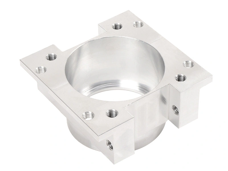
The structure of the part strongly affects what tolerance can be held consistently. Thick, rigid parts are usually easier to machine accurately than thin-wall housings, long slender shafts, deep pockets, or parts with many intersecting holes. Flexible geometry can move during clamping or cutting, which makes tight control harder even when the machine itself is precise.
This is why two parts made on the same machine can have very different tolerance limits. A simple block with a few drilled holes is usually easier than a thin aluminum housing or a small multi-feature connector body. Good tolerance planning should always consider how rigid the part is during machining.
4. Material Choice Also Changes What Tolerance Is Practical
Material affects CNC precision because different alloys respond differently to heat, tool pressure, burr formation, and internal stress. Aluminum may machine quickly but thin walls can distort more easily. Stainless steel may hold structure well but creates more tool load and burr risk. Titanium adds heat and tool wear. Brass may machine very cleanly and support strong thread accuracy. This means the same tolerance may be easier in one material and much more expensive in another.
That is why material choice and tolerance planning should be linked. Buyers can reduce unnecessary cost by choosing a material and tolerance combination that matches the real function of the part instead of applying the same tight specification to every alloy.
Main Influence | How It Affects Precision | Typical Result |
|---|---|---|
Part rigidity | Thin or flexible features move more during machining | Tighter tolerances become harder and more expensive |
Material behavior | Different alloys react differently to heat and tool load | Precision level changes by material |
Process route | Machining alone versus grinding or finishing | Selected features can achieve tighter size and better finish |
Inspection method | Critical geometry needs stronger verification | Better control of actual functional accuracy |
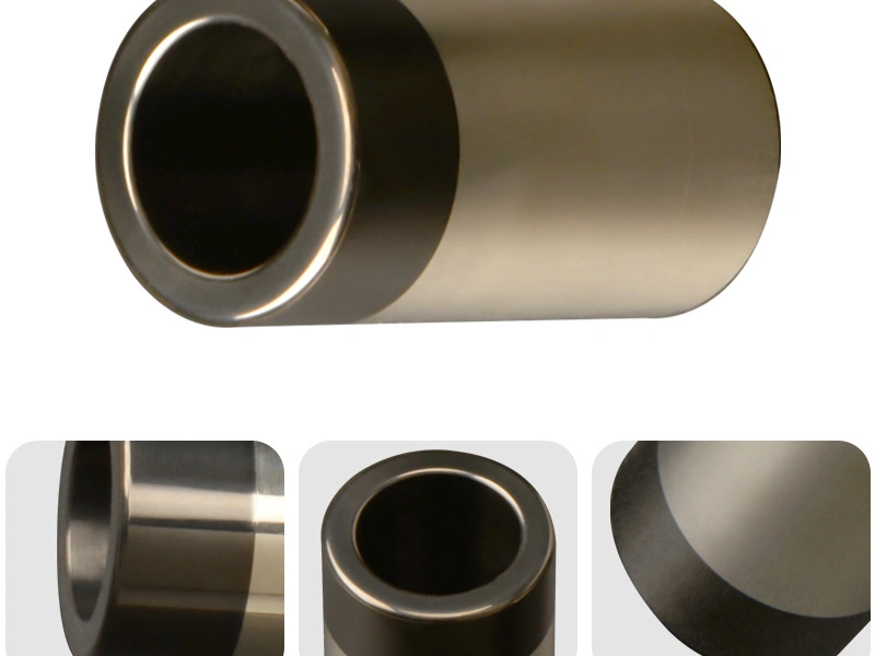
5. Process Choice Such as Grinding Can Push Selected Features to Higher Precision
Standard CNC machining already covers a wide tolerance range, but some parts need tighter control than milling or turning alone can deliver efficiently. In those cases, CNC grinding is often added for bearing diameters, fit bores, journals, and other critical surfaces where roundness, size stability, and lower roughness matter together. Grinding is especially valuable when the buyer needs fine control on only a few key features rather than on the entire part.
This is why many high-precision parts are not defined only by one process. They may use CNC machining for the main geometry and grinding or surface refinement for the most sensitive working surfaces.
6. Why Tolerance Planning Matters for Cost and Delivery
Tolerance planning matters because tighter tolerances increase machining time, inspection effort, setup sensitivity, and sometimes scrap risk. If the drawing applies very tight control to features that do not affect fit or function, the buyer may pay more without gaining real product value. On the other hand, if a truly critical bore or locating face is left too loose, the part may create assembly or performance problems later.
The best tolerance plan is therefore selective. It keeps tight control where the part function really needs it and uses more practical ranges where the feature is less critical. This approach improves both manufacturing efficiency and technical confidence.
7. Buyers Should Ask for Functional Tolerance Planning, Not Just Tight Numbers
The smartest way to plan CNC part precision is to link tolerance to the real job of the feature. A shaft fit, sealing diameter, or locating hole may justify a tight band. A non-critical exterior face may not. When buyers discuss tolerance this way, the supplier can often recommend a more balanced process route that keeps the important features stable while reducing unnecessary cost elsewhere.
This is one reason why early engineering discussion is so valuable. Good tolerance planning improves quality, lowers risk, and prevents over-specification before the part reaches production.
8. Summary
In summary, CNC machined parts typically achieve general tolerances around ±0.02 mm to ±0.05 mm on many standard features, while tighter critical features may often be controlled around ±0.005 mm to ±0.01 mm when the geometry, material, process, and inspection are well managed. Surface roughness also varies by process, with common as-machined finishes often around Ra 1.6 μm to 3.2 μm and finer values available through refined machining, grinding, or surface finishing.
The most important lesson is that precision depends on the actual feature, not just on the machine. Part structure, material, and process route all influence what is realistic. That is why good tolerance planning matters so much: it helps buyers get the accuracy they truly need without adding unnecessary cost or lead-time pressure to the project.