What Are CNC Machined Parts and Why Are They Used So Widely?
What Are CNC Machined Parts and Why Are They Used So Widely?
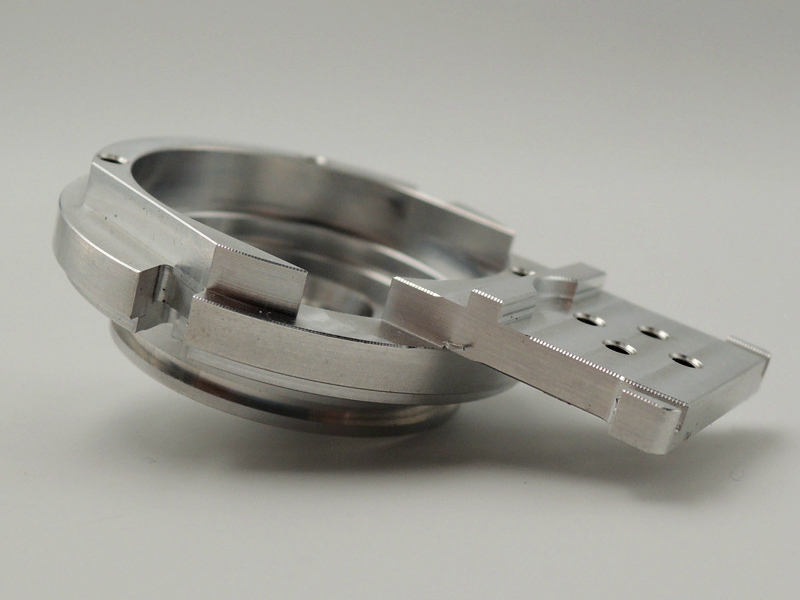
CNC machined parts are finished components cut from solid stock by computer-controlled milling, turning, drilling, boring, or threading operations. They are used widely because one digital route can produce functional features in many metals and plastics without dedicated forming tooling. This advantage applies when tools can reach the geometry and the stock, workholding, and inspection plan support the drawing. A CNC program alone does not guarantee conformity. The RFQ must identify material condition, functional datums, critical interfaces, finish, quantity, and acceptance evidence.
CNC machining suits housings, brackets, shafts, plates, and connectors whose fit depends on relationships between bores, faces, holes, threads, and sealing surfaces. It can serve development and repeat orders, but tool access, setup changes, thin-wall movement, cutting forces, and inspection uncertainty remain limits. Process selection should follow function and validation risk, not a general claim that CNC is always more precise.
1. CNC Machined Parts Convert Digital Geometry into Controlled Material Removal
A CNC machined part begins as stock with a defined grade, condition, and form. A programmer converts the model and drawing into operations, tools, setups, cutting parameters, and inspection checkpoints. Roughing removes bulk material; finishing controls selected interfaces. Milling suits prismatic faces, pockets, and hole patterns, while turning suits features organized around a rotational axis. Drilling, boring, threading, deburring, finishing, or grinding may complete the route.
Digital control makes commanded motion repeatable, not every production result. Tool wear can change size and burr formation; workholding can distort a thin feature; and a second setup can shift a datum relationship. ASME Y14.5 communicates dimensional and geometric requirements on the drawing, but it does not certify a machine or supplier. Each functional requirement still needs a controllable operation and a suitable measurement.
Part Family | Functional Relationship to Control | Evidence Needed Before Release |
|---|---|---|
Housing | Bore location to mounting face and port datums | Datum plan, setup sequence, and bore-to-face inspection |
Bracket | Hole position, angle, and unclamped contact faces | Fixture method and free-state inspection where function requires it |
Shaft | Diameters, shoulders, and runout to the datum axis | Operation route, datum axis, and specified runout check |
Plate | Flatness, thickness, and hole-pattern relationship | Stock condition and measurement after unclamping |
Connector | Thread, sealing face, and mating geometry | Thread gauge plus surface or leak test when specified |
2. Housings Show Why Feature Relationships Matter
Machined housings are common because they locate components while connecting several interfaces in one body. A housing may combine bearing bores, ports, threads, a sealing face, and mounting datums. Planned milling and boring setups can establish these features, but acceptance depends on their final relationship after unclamping. A bore measured alone does not prove alignment with the mounting or sealing interface.
Thin walls can move after roughing, and re-fixturing can transfer error between internal and external features. The process plan should leave finishing stock, stabilize the datum scheme, and inspect the functional relationship in final condition. The RFQ should mark mating features and state whether sealing, bearing alignment, or assembly clearance drives acceptance.
3. Brackets and Plates Expose Workholding and Distortion Risk
Brackets and plates position other components through hole location, contact-face orientation, slot position, and structural stiffness. CNC machining can control these relationships from common datums when the fixture supports the part without hiding free-state distortion. A drawing must therefore communicate how the part functions in assembly, not only its individual feature sizes.
A thin plate can appear flat while clamped and move after release. Pocketing can redistribute residual stress, shifting a hole pattern relative to a contact face. Tighter dimensions do not correct that mechanism. Choose the stock condition, balance roughing, stabilize when necessary, finish from functional datums, and inspect in the specified condition. Quote review should separate free-state requirements from assembly clamping conditions.
4. Shafts and Connectors Depend on Interface Control
Machined shafts and connectors support rotation, guidance, threaded assembly, or sealing. Turning can produce diameters and shoulders from a common axis; live tooling or another setup can add flats, cross-holes, slots, or ports. The drawing must distinguish size, straightness, surface texture, and runout because each controls a different part of function.
Failure often appears at the interface. Tool wear can alter a thread or leave an assembly-blocking burr. A sealing face may meet size requirements yet leak when damage crosses the seal path. Verification may combine calibrated size measurement, specified thread gauges, runout inspection, visual criteria, and a functional leak test. The RFQ must name the mating standard, seal type, and test condition instead of requesting a vague "precision connector."
5. Broad Use Comes from Adapting One Process to Different Failure Risks
CNC machining adapts digital toolpaths, workholding, and available stock forms to different functional risks. Automotive work may emphasize assembly position and controlled production changes. Medical device parts may add buyer-defined traceability, surface, cleanliness, and documentation requirements. Industrial and consumer parts use similar manufacturing principles but different release evidence.
CNC does not automatically meet every industry rule. A housing needs different evidence when it locates a cosmetic cover, supports a bearing, or forms a pressure boundary. Measurement conditions matter too: ISO 1:2022 sets the dimensional and geometrical product specification reference temperature at 20 degrees C. The inspection plan should identify any temperature, fixturing, sampling, or functional test that affects release.
Use Context | Failure Consequence to Prevent | Release Evidence to Define |
|---|---|---|
Automotive | Assembly mismatch or uncontrolled production change | Drawing inspection and customer-required approval records |
Medical | Incorrect interface, material, surface, or cleanliness state | Traceability and documented inspection to buyer requirements |
Industrial Equipment | Wear, misalignment, leakage, or difficult field assembly | Critical-feature inspection and relevant functional test |
Consumer Products | Visible defects or inconsistent fit between assemblies | Approved cosmetic limit and mating-part fit check |
6. CNC Supports Prototypes and Repeat Orders, but the Controls Must Change
CNC machined parts can move from development samples to repeat orders because the model, drawing, program, tooling logic, and inspection plan can be revised without a permanent mold or die. That flexibility supports testing while designs change, but it does not eliminate setup engineering. Even one part needs verified stock, workholding, offsets, tool access, deburring, and inspection.
A proven prototype program is not a complete production control plan. Repeat orders add tool-life limits, replacement stock lots, fixture loading, revision control, sampling, and drift reaction rules. A prototype may be approved by fit and critical-feature inspection. Repeat production may also require an approved first article, defined sampling, measurement-system evidence, or process records when the buyer or industry program specifies them.
7. CNC Is Valuable When Precision and Flexibility Outweigh Its Limits
CNC is a strong choice for production-grade stock, accessible features, controlled interfaces, and quantities that do not justify dedicated forming tooling. It also accommodates revisions through updated programs and fixtures. Material removal creates limits: deep cavities add time and waste, internal corners reflect tool geometry, and hidden features may require extra setups or another process.
Compare the complete route. Casting, forging, or molding may lower recurring cost after demand stabilizes, although critical interfaces may still need machining. Additive manufacturing can create inaccessible internal passages, while fabrication may suit large structures made from simpler pieces. A hybrid route can outperform a forced single process. The quote should identify which features are machined, formed, printed, joined, finished, and inspected.
8. Make the RFQ Prove That CNC Is the Right Route
CNC machined parts are widely used because computer-controlled material removal creates functional geometry from many stock materials without dedicated forming tooling. Their value comes from interface control and a route that can evolve from prototypes to repeat production. Tool access, setup transfer, cutting forces, stock behavior, and measurement uncertainty remain limits that require explicit controls.
A release-ready RFQ identifies material grade and condition, model and drawing revision, functional datums, critical dimensions, geometric controls, surface requirements, quantity stages, post-processing, mating conditions, and acceptance records. The supplier can then decide whether CNC machining is the complete route or one step in a hybrid process. For automotive or medical device work, state project-specific approval and traceability requirements before quotation.