How Can Brass Machining Services Prevent Burrs, Surface Damage, and Dimensional Variation?
How Can Brass Machining Services Prevent Burrs, Surface Damage, and Dimensional Variation?
Brass machining services prevent burrs, surface damage, and dimensional variation by controlling edge formation, tool condition, workholding, chip movement, deburring, handling, and inspection together. Controls must match the brass grade, feature geometry, datum scheme, functional surfaces, and delivery state. Final deburring cannot protect a distorted bore or damaged seal face. The RFQ should identify critical edges, surfaces, dimensions, inspection state, and acceptance evidence.
For CNC machining and CNC turning of brass, connect each defect source to a control limit and reaction. First-article checks establish the route; in-process checks detect drift; final inspection follows deburring, cleaning, finishing, and thermal stabilization. A burr-free promise is not a release plan.
1. Map Burr Risk by Exit Direction and Feature Function
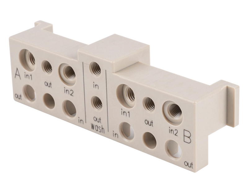
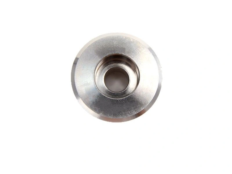
Brass burrs concentrate where a cutting edge leaves supported material: hole exits, cross-hole intersections, thread starts and runouts, slot exits, and cutoff edges. Burr direction and consequence depend on tool travel, material support, edge wear, and feature function. A projection may block assembly, damage a seal, enter a fluid path, or remain harmless on a nonfunctional edge.
Mark risk locations during drawing review, then plan operation order, exit direction, local support, and edge access. Where practical, let the tool exit into supported stock or a later-removal surface. Inspect the complete first-article edge with magnification, a borescope, a replica, or another method suited to access and the specified limit.
Defect Location | Likely Mechanism | Required Control and Evidence |
|---|---|---|
Cross-hole or bore intersection | Breakthrough into an unsupported internal edge | Plan sequence and inspect the complete intersection |
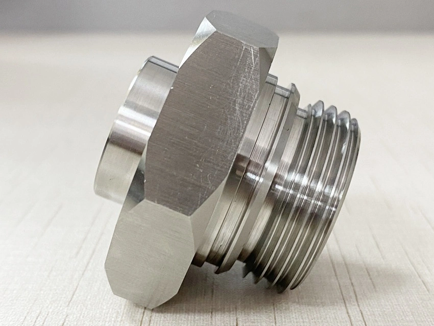
Thread start or runout | Entry, exit, or crest material displacement | Define the edge and gauge the thread after deburring |
Parting or slot exit | Unsupported final material or worn cutting edge | Control the exit and verify edge plus adjacent size |
Seal or cosmetic face | Chip recutting, jaw mark, or part contact | Protect the zone and inspect its final functional state |
2. Tie Tool Condition to a Measurable Defect Trigger
Tool condition affects burr height, cutting force, thread form, finish, and dimensional trend, but sharpness is not a complete specification. Tool geometry must suit the brass grade, operation, feature rigidity, and machine. A geometry that cuts one free-machining brass cleanly may grab, rub, or form different chips in another composition or temper.
Set replacement triggers from edge-condition growth, surface change, spindle-load trend, thread-gauge response, or dimensional movement. Record tool identity, operation, inspected feature, interval, and reaction. Replace or correct the tool before the limit is crossed; do not assign universal life or cutting speed without a qualified trial.
3. Workholding and Cut Sequence Control Released Dimensions
Dimensional variation can come from clamping distortion, insufficient support, tool deflection, roughing stress, part temperature, or a changed datum relationship. Thin walls may measure correctly while clamped, then move after release. A machine offset cannot correct fixture- or sequence-induced movement.
Locate from the specified datum without crushing the feature. Separate roughing and finishing when removal or heat changes stability, and release or reclamp before final cuts when validation shows movement. Compare clamped and unclamped first-article results, then inspect the released part from the drawing datum after all dimension-changing operations.
4. Control Chip Paths and Part Contact Around Finished Surfaces
Short brass chips can scratch a bore, seal face, thread, or cosmetic surface when they recut or lodge under a jaw. Finished parts may also touch in a bin, and contamination may remain before polishing or plating. The control plan must follow chips and contact surfaces through each setup, transfer, wash, and pack step.
Choose coolant, air, vacuum, or mechanical evacuation after checking grade, geometry, cleanliness, and downstream compatibility. Clean locators, protect designated surfaces, and separate parts when contact marks are unacceptable. Inspect after the final process that can alter appearance or function, not only when the part leaves the machine.
Control Gate | Failure Trigger | Release Action |
|---|---|---|
Edge condition | Burr exceeds the drawing limit or blocks function | Correct the source and reinspect the edge and neighbor feature |
Surface condition | Mark appears in a seal, contact, or cosmetic zone | Segregate parts, trace the source, and verify final function |
Dimensional trend | Result approaches the control limit or moves after release | Correct tool or setup and reconfirm datum and temperature |
Deburr or finish | Edge break, thread, bore, or surface changes | Repeat dimensional, gauge, surface, or functional acceptance |
5. Deburr Without Recutting the Functional Feature
Deburring must remove the projection without rounding a locating edge, enlarging a bore, changing a thread start, or scratching a seal. Manual, brushing, tumbling, abrasive, thermal, and electrochemical methods remove material differently. Select the method from geometry, burr location, cleanliness, finish, volume, and prohibited feature change rather than material name alone.
ISO 13715:2017 provides a drawing language for indicating and dimensioning edges of undefined shape; it does not supply a default edge-break size. Define permitted edge condition, protected edges, chamfers or radii, and inspection method. After deburring, recheck every adjacent critical diameter, thread, seal, contact, or cosmetic zone that the process can alter.
6. Define the Thermal and Release State for Dimensional Acceptance
ISO 1:2022 sets 20°C as the standard reference temperature for geometrical and dimensional specification and verification when it applies. A brass part measured hot from cutting or washing may not represent reference-state size. Stabilization depends on mass, temperature difference, environment, measurement uncertainty, and tolerance.
State whether inspection occurs unclamped, after deburring, after finish, or assembled. Trend critical dimensions and define a reaction before the acceptance boundary is reached. Final inspection cannot recover a drifting process; it separates observed conforming and nonconforming results under stated conditions.
7. Separate Cosmetic Zones from Functional Surface Requirements
Cosmetic faces, sealing surfaces, bearing fits, and electrical contacts need different acceptance rules. No scratches is vague without a zone, viewing or measurement method, and limit. Functional surfaces may need roughness, flatness, leakage, fit, or contact-resistance verification after the final wash, coating, plating, or assembly.
Mark surface classes on the drawing and use an approved sample when appearance controls the decision. Protect functional zones during polishing and plating, then inspect the delivered state by the agreed method. Packaging must preserve that condition through shipment.
8. Summary
Reliable brass defect prevention starts with a feature risk map and ends with final-state evidence. Control tool condition, exit direction, workholding, datum recovery, chip paths, deburring, cleaning, handling, temperature, and inspection as connected steps. Release records must show that the edge, nearby dimension, surface, and function still conform after secondary processing.
For machining and turning, send the drawing revision, brass grade, datum scheme, critical edges, protected surfaces, tolerances, finish state, measurement temperature, sampling plan, and functional tests. Evaluate a brass machining service by its defect triggers, reaction plan, and release evidence, not by a generic burr-free claim.