
Why Is Precision Machining Critical for Oil and Gas Sealing and Flow Control Parts?
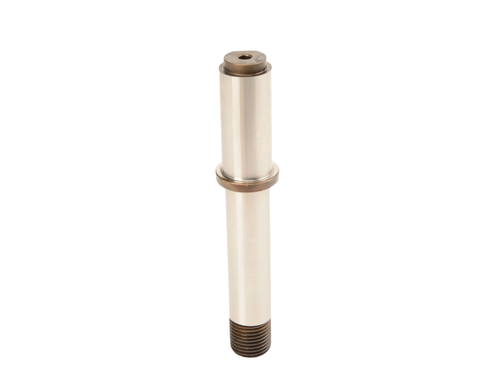
Why Is Precision Machining So Important for Sealing, Flow Control, and Reliability in Oil and Gas Parts?
Precision machining is critical in oil and gas parts because it controls the geometric relationships that create seal contact, effective flow area, alignment, actuation, and predictable wear. Precision does not mean making every dimension unusually tight. The required size, form, orientation, position, surface texture, and edge condition depend on the seal design, fluid, pressure, temperature, load, material, coating, and assembly. Buyers should identify functional characteristics and acceptance evidence in the RFQ instead of requesting a general “high-precision” part.
Effective CNC machining connects the drawing datum scheme, process sequence, workholding, tool-wear reaction, deburring, final-state inspection, and functional test where specified. For cylindrical interfaces, CNC turning can create related diameters, faces, grooves, and threads from a controlled axis. Machine positioning specifications still do not guarantee part results. Procurement should ask how the supplier will verify each critical relationship after unclamping and after heat treatment, coating, or other operations that can change it.
1. Precision Directly Controls Sealing Performance
Sealing performance depends on the correct combination of contact geometry, surface condition, material behavior, assembly load, and operating environment. A diameter within size tolerance can still leak when roundness is poor. A flat face can still fail when its orientation to the bore or bolt pattern produces uneven compression. Surface roughness alone does not describe waviness, lay, damage, or edge discontinuities. The seal manufacturer, component design, governing specification, and responsible engineer must define the functional limits; machining must reproduce and verify them.
Build a sealing-characteristic matrix before production. Identify the primary and secondary seal surfaces, mating datum, size and geometric controls, texture parameter, edge break, coating or plating state, cleanliness, and permitted defects. State whether inspection occurs before or after coating and whether a leak or pressure test is required. A functional test proves performance only under its stated medium, pressure, temperature, duration, setup, and acceptance limit. It does not replace dimensional evidence or validate untested service conditions.
Functional Area | Why Precision Matters | Failure Risk If Out of Control |
|---|---|---|
Sealing face | Flatness, profile, orientation, texture, lay, damage, and edge condition govern contact distribution | Local contact loss, extrusion path, unstable preload, or leakage |
Bore or seat diameter | Size, roundness, cylindricity, taper, and relation to the seat control clearance and shutoff geometry | Bypass flow, seal damage, sticking, or inconsistent closing load |
Threaded connection | Form, pitch diameter, lead, flank condition, runout, shoulder relation, and cleanliness control assembly | Galling, false torque, poor engagement, misalignment, or a leak path |
Concentric diameter | Related axes and faces keep seals, stems, guides, and rotating interfaces loaded as designed | Eccentric contact, friction, vibration, accelerated wear, or unstable actuation |
2. Flow Control Also Depends on Machining Accuracy, Not Just Design Intent
Flow control depends on the manufactured area, profile, position, transition, and surface condition of ports, seats, orifices, stems, spools, and internal passages. A drawing may define the nominal flow path, but size drift, offset intersections, remaining burrs, distorted bores, or incorrect edge geometry can change effective area and local turbulence. Machining accuracy protects the design intent only within the model and test assumptions. It cannot by itself certify flow coefficient, pressure drop, erosion life, or cavitation performance.
Define which dimensions govern open area, shutoff, stroke, overlap, and alignment, then connect them to an inspection or test method. A borescope may confirm an internal burr is absent but not measure a tight diameter accurately. A coordinate measuring machine may locate an accessible port but miss hidden edge condition. Flow testing can validate assembled behavior at stated conditions, while dimensional reports support root-cause control. The RFQ should state required cleanliness, edge breaks, internal inspection access, test fluid, test points, and acceptance limits.
3. Small Machining Errors Can Grow into Large Equipment Risks
Small machining errors become equipment risks when tolerance stack, pressure, temperature, vibration, corrosion, assembly load, and wear act on the same functional chain. A slightly off-axis stem can load one side of a guide, increase friction, mark a seal, and later create bypass leakage. A port-edge burr can detach, obstruct a restriction, damage a seat, or contaminate another component. The initial deviation is not automatically dangerous; risk depends on its location, direction, mating parts, service conditions, and remaining design margin.
Use a feature-to-failure review instead of applying the same tolerance to every surface. Trace each sealing, guiding, locating, fastening, and flow feature through its mating stack. Identify the worst credible combination and the operation that can create it. Then assign prevention, in-process reaction, final verification, and functional validation. Any tolerance change, repair, alternate coating, or datum interpretation should return to the responsible design authority because manufacturing convenience does not establish acceptable system risk.
4. Functional Surfaces Matter More Than Cosmetic Surfaces
Functional surfaces deserve priority because they transmit load, locate components, contain fluid, guide motion, or set flow. Visual finish can support handling and corrosion protection, but appearance does not establish flatness, roundness, thread form, profile, or alignment. Marking, blasting, polishing, coating, and packaging can also damage a working surface after it was measured. The control plan should identify protected zones, masking, handling methods, final condition, and the inspection stage for every critical surface.
A useful drawing distinguishes functional characteristics from reference, stock, and cosmetic requirements without leaving appearance undefined. Apply the datum structure that represents assembly function, and avoid measuring each feature from convenient local surfaces that do not reproduce the mating relationship. When a coating changes size or texture, specify whether dimensions apply before or after coating. Buyers should review a ballooned characteristic plan before release and confirm that the chosen method can reach and resolve the required feature.
Surface Type | Priority Level in Oil and Gas Parts | Main Reason |
|---|---|---|
Sealing surfaces | Risk-based critical when they form or support the leakage barrier | Require defined geometry, texture, damage limits, mating relation, and final-state evidence |
Threads and mating shoulders | Risk-based critical when they create preload, alignment, or pressure containment | Gauge result alone may not cover shoulder relation, runout, damage, cleanliness, or torque behavior |
Bores and functional diameters | Risk-based critical when they guide, meter, locate, seal, or control clearance | Size must be evaluated with form, axis relation, taper, final state, and mating tolerance stack |
External cosmetic faces | Defined by corrosion, handling, marking, or appearance requirements | Lower functional priority does not permit damage that reaches protected edges, seals, threads, or coating |
5. Precision Improves Reliability by Controlling Fit, Contact, and Wear
Precision improves reliability when it produces the intended clearance, interference, preload, alignment, and contact pattern across the full operating range. Room-temperature assembly fit may change under differential thermal expansion, pressure deformation, coating thickness, lubrication, contamination, or material pairing. An excessively tight guide can stick; excessive clearance can tilt a stem or permit impact. Correct limits come from the design analysis and service envelope, not from a generic machining capability. The supplier must control the dimensions and relationships assigned by that analysis.
Wear is both a material and geometry problem. Misalignment concentrates load, rough or damaged surfaces disturb lubrication, and tool-wear drift can gradually change clearance through a lot. Stainless and nickel-alloy threaded pairs may gall even when pitch diameter passes, depending on finish, cleanliness, lubrication, engagement, and assembly. Monitor drift-sensitive characteristics during machining, define tool-change and nonconformance reactions, and verify parts after unclamping. Trend data can support process control, but only measured characteristics and authorized acceptance rules release the product.
6. Precision Turning Is Especially Important for Cylindrical Oil and Gas Parts
Many oil and gas sealing and flow-control parts depend on a common functional axis, which makes precision turning important for related diameters, shoulders, grooves, tapers, and threads. Producing related features in one controlled setup can reduce datum-transfer error, but it does not remove tool deflection, thermal growth, chuck distortion, thin-wall movement, or measurement uncertainty. The process plan should identify which features share a setup and how later milling, heat treatment, coating, or rechucking affects that relationship.
Do not use runout, concentricity, coaxiality, cylindricity, and position as interchangeable terms. The drawing should invoke the applicable ASME Y14.5 or ISO GPS framework and define the functional control. Inspection must establish a datum representation suitable for the part, not merely rotate it on a convenient surface. Threads also need their relationship to seals and shoulders verified where function requires it. Measure flexible or clamped diameters in the specified free or restrained state and document that state with the result.
7. Precision Machining Reduces the Risk of Hidden Field Failure
Precision machining reduces hidden field risk only when prevention and verification cover the actual failure modes. Visual inspection will not reveal a lobed bore, datum shift, incorrect thread lead, waviness, internal burr, or mixed material heat. A final report can also give false confidence when the method, fixture, temperature, sampling, or characteristic mapping is unsuitable. Buyers should request the released revision, material traceability, process and inspection plan, actual critical results, method status, nonconformance closure, and any specified leak, pressure, torque, or flow evidence.
Supplier workflow should connect contract review, material identity, setup approval, in-process checks, deburring and cleaning, outside processes, final-state inspection, exception review, testing, and release. Ask who owns each hold point and what happens when a result trends or fails. A useful RFQ lists mating relationships, critical characteristics, seal or flow function, material and condition, coatings, quantities, lot definition, reporting coverage, test conditions, and acceptance authority. That information lets the supplier quote a verifiable route instead of promising unspecified precision.
8. Summary
Precision machining protects sealing, flow control, and reliability in oil and gas parts by controlling the size, form, orientation, position, texture, and edge conditions that govern contact, clearance, alignment, and effective flow area. Tight tolerances are valuable only on functionally justified characteristics and only when the manufacturing and inspection methods can reproduce them. Pressure, temperature, coating, assembly, contamination, and wear remain part of the engineering boundary.
Buyers should qualify precision CNC machining and precision turning through a feature-to-failure matrix, final-state characteristic plan, suitable measurement methods, traceable actual results, exception closure, and specified functional tests. Send the exact material, condition, drawing framework, mating interfaces, service limits, critical features, coating state, quantities, document coverage, and acceptance authority with the RFQ. This turns “precision” from a marketing label into an auditable manufacturing requirement.



