
Which Machining Processes Deliver the Best Precision for Oil and Gas Components?
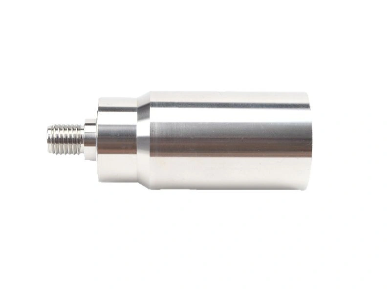
Which Machining Processes Deliver the Best Precision for Oil and Gas Components?
The best machining route for an oil and gas component usually combines turning or milling to establish functional datums, drilling and related hole-finishing methods for ports and passages, and grinding or another justified finish process for selected final surfaces. No process is universally most precise. The correct choice depends on material and condition, stock form, feature geometry, access, tolerance definition, surface requirement, later processing, and inspection method. Buyers should request a feature-by-feature route and final-state validation plan with the RFQ.
Process capability is specific to the machine, tool or wheel, workholding, environment, program, operator controls, batch, and measurement system. A nominal machine accuracy or process label does not guarantee part tolerance. Oil and gas components also contain interacting features: a thread may reference a turned axis, a drilled passage may intersect a milled port, and a ground seal diameter may change after coating or handling. The route must preserve datum relationships, material identity, cleanliness, edge condition, and inspection access through every transfer.
1. Turning Is Often the Best Process for Cylindrical Precision Features
CNC turning is often the primary process for cylindrical diameters, faces, shoulders, grooves, tapers, and threads that share a functional axis. Keeping related features in one controlled setup can reduce datum-transfer error. Suitability still depends on length-to-diameter ratio, wall thickness, interrupted cuts, feature access, material condition, chucking, and tool deflection. A long stem can bend, a thin sleeve can distort in the chuck, and a difficult alloy can change size or finish as the tool wears.
The turning plan should identify rough and finish datums, clamping surfaces, support method, tool-wear limits, thermal control, chip and burr risks, and the inspection state. Measure flexible diameters after unclamping unless the drawing specifies a restrained condition. Threads need form, pitch diameter, lead or relationship, runout, damage, and cleanliness controls as required; one go/no-go gauge does not prove every function. Later milling, heat treatment, grinding, or coating may require the critical axis relationships to be checked again.
Machining Process | Best At Controlling | Typical Oil and Gas Part Types |
|---|---|---|
Related cylindrical sizes, faces, grooves, tapers, and threads when setup and material behavior are controlled | Connector bodies, stems, sleeves, bushings, fittings, shafts, and sealing carriers | |
Milling | Datum faces, patterns, pockets, profiles, slots, and multi-face relationships with planned access | Valve bodies, housings, manifolds, blocks, flanges, and mounting structures |
Initial holes and passages whose position, depth, straightness, breakthrough, and edge condition are validated | Flow connectors, valve bodies, manifolds, lubrication paths, and instrumentation ports | |
Selected final sizes, forms, and textures after stock, heat, support, and wheel conditions are qualified | Shaft journals, seal diameters, wear sleeves, guide surfaces, and specified contact faces |
2. Milling Is Critical for Valve Bodies, Housings, and Multi-Face Structural Parts
Milling is critical when valve bodies, housings, manifolds, or interface parts need related datum faces, mounting patterns, pockets, profiles, slots, or off-axis features. Three-axis, indexed, or simultaneous multi-axis strategies solve different access and setup problems; more axes do not automatically improve accuracy. The route should minimize harmful datum transfers while maintaining workholding stiffness, tool access, chip evacuation, and inspectability. A large open face and a deep pocket on the same part can have very different deflection and thermal behavior.
Face flatness does not prove its orientation to a bore or port pattern. A pocket size does not prove wall thickness, profile, or position. The milling plan should state the datum sequence, stock allowance, roughing and stress-release logic where required, critical tool reach, in-process checks, and final characteristic map. Thin walls may move after clamps are released. If coating, heat treatment, or pressure testing can alter geometry, identify which faces and patterns need final-state re-verification before shipment.
3. Drilling Is Essential for Flow Paths, Ports, and Critical Hole Location
CNC drilling is essential for creating initial holes, ports, and passages, but drilling alone may not deliver final diameter, form, straightness, texture, or thread quality. Boring, reaming, honing, threading, or another finish operation may be needed when the feature function requires it. Method choice depends on depth-to-diameter ratio, material, access, breakthrough, intersecting passages, tolerance, and inspection. Buyers should avoid specifying “precision drilling” without defining the hole's functional characteristics.
For a cross-drilled valve or manifold body, the control plan should cover entry position, angle, depth, straightness, intersection overlap, minimum wall, tool breakout, burr removal, chip removal, cleaning, and verification. A correct external position can coexist with an internal burr or incomplete intersection. A borescope can inspect visible edge condition but may not prove diameter or straightness. The RFQ should define allowed edge breaks, cleanliness, plugs or closures, internal inspection access, actual-value coverage, and any flow or pressure test conditions.
4. Grinding Delivers the Highest Finish and Geometry Control on Critical Wear and Sealing Surfaces
CNC grinding can deliver tight final size, form, and surface texture on suitable accessible features, but it is not automatically the highest-precision solution for every oil and gas surface. Material hardness, prior heat treatment, stock allowance, wheel specification and condition, dressing, coolant, support, thermal control, and measurement govern the result. Grinding can introduce burn, residual stress, cracks, chatter, or unfavorable lay when the process is not qualified.
Use grinding when the functional requirement and process chain justify it. Specify the final diameter or profile, roundness or runout if needed, texture parameter and cutoff, damage limits, coating state, and datum relationship. Confirm whether grinding occurs before or after heat treatment and how remaining stock is controlled. The supplier should monitor wheel and thermal behavior and verify the part after unclamping. A fine roughness number does not by itself prove waviness, form, axis alignment, seal contact, or service performance.
Functional Requirement | Most Suitable Process | Why |
|---|---|---|
Related diameters and threads | Can establish axis-based features in controlled setups, subject to clamping, deflection, tool, and final-state limits | |
Datum faces and structural pockets | Milling | Provides planned access to planar, profile, pattern, and multi-face features with explicit datum transfers |
Ports and intersecting fluid holes | Creates the initial passage; secondary sizing, threading, deburring, cleaning, inspection, or testing may complete function | |
Selected sealing and wear surfaces | Can refine final size, form, and texture when stock, heat, wheel, support, and damage controls are qualified |
5. Many Oil and Gas Parts Require a Multi-Process Route, Not a Single Operation
Many oil and gas components need a multi-process route because their functional features have different access, geometry, material-state, and surface requirements. The route must also decide when to create and protect datums. Turning a connector axis before drilling a cross port may simplify location, but the port can leave an internal burr that threatens the flow path. Grinding a seal diameter before a later coating or aggressive handling may invalidate the final result. Sequence is therefore an engineering control, not only a scheduling choice.
Map every operation to its input condition, output characteristic, inspection point, and change risk. Include raw-material identity, rough machining, stress relief or heat treatment when specified, finish machining, threads, deburring, cleaning, NDE, coating, final inspection, functional testing, and document release as applicable. Identify outside processors and hold points. When a later operation changes size, texture, form, or datum relationship, repeat the affected verification instead of relying on an earlier passing report.
6. Typical Application Scenarios Show Why Process Selection Must Match the Part Function
Consider a corrosion-resistant connector with an external thread, internal seal diameter, shoulder, and cross-drilled passage. Turning may establish the thread, shoulder, and seal-axis relationship; hole-making creates the passage; controlled deburring and cleaning protect the internal path. Grinding is justified only if a final size, form, or texture requirement needs it after material-state changes. The process plan should verify the thread-to-seal relationship, passage intersection, remaining wall, internal edge, cleanliness, and final seal geometry.
A valve body follows a different route. Milling may establish mounting and assembly datums, drilling and finishing create ports and guide bores, and a suitable turning, boring, grinding, lapping, or other method finishes selected seats or guides. The route must preserve alignment across setups and leave access for inspection. These examples are decision models, not Neway customer cases. The actual sequence must come from the released drawing, material condition, equipment, risk review, and sample validation.
7. Process Combination Also Improves Inspection Logic and Part Reliability
A well-designed process combination creates meaningful inspection gates, but adding operations does not automatically improve reliability. Establish material and datum identity first, measure characteristics that control the next irreversible step, and reserve final acceptance for the final functional state. In-process measurements guide reactions and protect stock; they do not replace required final evidence. The control plan should state characteristic, method, frequency, datum or restraint, reaction limit, record, and approval owner at each gate.
Inspection must remain independent of process assumptions. A turned diameter needs suitable size and form evidence; a milled pattern needs the defined datum alignment; a drilled passage needs internal edge and cleanliness verification; a ground surface needs form, texture, and damage review. Measurement uncertainty and access must suit the tolerance. Buyers should request actual results for critical features, link records to part or lot identity, and require written disposition for any route or acceptance deviation.
Typical Part | Most Effective Process Combination | Main Reason |
|---|---|---|
Connector body | Turning + Drilling | Preserves thread, shoulder, seal-axis, passage-intersection, burr, and cleanliness relationships |
Valve body | Milling + Drilling + Turning | Connects assembly datums, ports, guides, seats, and sealing features through planned transfers and verification |
Sealing shaft or sleeve | Turning + Grinding | Creates the axis and stock condition before justified final size, form, texture, and damage control |
Instrumentation interface block | Milling + Drilling | Relates mounting faces, patterns, threads, and passages while controlling intersections and remaining wall |
8. Summary
The best precision for oil and gas components comes from matching turning, milling, drilling, and grinding to specific features and states. Turning often establishes related cylindrical geometry, milling creates faces and multi-axis features, drilling begins ports and passages, and grinding can refine selected final surfaces. Each process has limits, failure modes, and measurement needs. The sequence must protect datums, material condition, edges, cleanliness, final geometry, and traceability.
Buyers should send the released drawing and specifications, exact material and condition, critical-characteristic ranking, coating or heat-treatment state, quantities, lot definition, required processes or approved sources, inspection coverage, functional tests, and acceptance authority. Ask suppliers to return a feature-process-state-inspection matrix with assumptions and exceptions. Compare the proposed routes on verifiable control of the finished part, not on machine specifications, process labels, or unsupported claims that one operation is always the most precise.



