
What Tolerances and Surface Finishes Can CNC Machined Parts Typically Achieve?
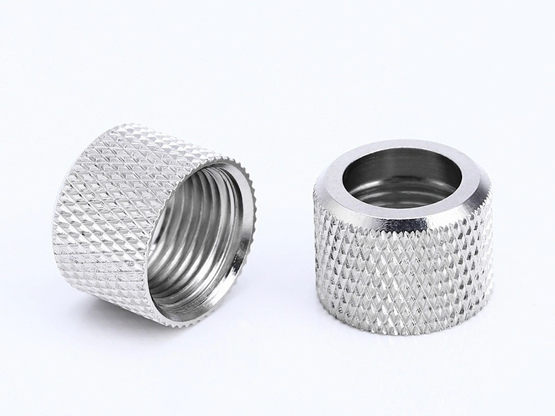
What Tolerances and Surface Finishes Can CNC Machined Parts Typically Achieve?
CNC machined parts can often be planned around ±0.05 mm bilateral for rigid, accessible, non-critical dimensions and Ra 3.2 µm for a suitable as-machined surface. Selected mating sizes may justify ±0.02 mm, while Ra 1.6 µm may require a controlled finishing pass. These are RFQ screening values, not capability guarantees; material, geometry, setup, final state, and inspection can change them. Bores or hardened datums may need boring, reaming, honing, or CNC grinding.
Ra excludes waviness, lay, burrs, damage, and geometric accuracy. State ISO 21920-2 texture parameters, datums, final finish state, and acceptance method. Use a profilometer for texture and separate methods for size or GD&T.
1. What Is a Typical Tolerance Range for CNC Machined Parts?
Use ±0.05 mm bilateral only as a baseline for rigid, accessible linear features measured after unclamping. Evaluate ±0.02 mm on a selected dimension or bore against its grade, geometry, datum route, and gauge. Profile, position, flatness, and run-out need separate GD&T zones.
ASME Y14.5 and ISO 1101 communicate geometric requirements, not supplier capability. Apply one drawing standard consistently, identify functional datums, and state whether limits apply before or after coating. Reserve tight controls for fit, sealing, alignment, motion, or interchangeability.
Requirement | Planning Basis | Acceptance |
|---|---|---|
Accessible linear dimension | ±0.05 mm bilateral for a rigid feature | Measure after unclamping at specified temperature |
Selected mating size | Evaluate ±0.02 mm by grade and geometry | Confirm finishing and calibrated gauge |
Precision bore or seat | Use fit limits, not generic tolerance | Match the finishing process to a bore gauge |
Feature-to-datum relation | Specify GD&T separately from size | Verify by CMM or functional gauge |
2. Which Factors Most Affect CNC Machining Accuracy?
CNC part accuracy depends on the process chain, not machine positioning or instrument resolution alone. Thin walls can spring after unclamping, heat shifts size, and tool wear changes dimensions and burrs. Datum transfer can alter relationships while local sizes pass.
Match inspection to the requirement. Micrometers and bore gauges check size. A CMM evaluates geometric relationships with suitable datum alignment and probing. A profilometer evaluates texture, not position. Identify critical characteristics, measurement, sampling, and reports in the RFQ.
Control Factor | Risk and Confirmation |
|---|---|
Material condition | Stress or temperature shifts size; confirm grade, temper, stock, and measurement condition |
Part geometry | Thin walls deflect; inspect after unclamping |
Tool and cutting strategy | Wear, runout, or vibration changes size and texture; control tool life |
Fixture and datum transfer | Distortion changes relationships; verify functional datums |
Measurement system | Wrong equipment hides defects; match gauge, CMM, or profilometer to the characteristic |
3. How Do Different Materials Change Tolerance Performance?
Material grade and condition change tolerance control. A 6061-T6 aluminum wall may move after stock removal. Austenitic stainless steel can work harden when a tool rubs. Titanium concentrates heat near the edge. Semicrystalline plastics respond to temperature and moisture. Each mechanism affects stability and inspection timing.
Review function and geometry before transferring tolerances between materials. Provide grade, condition, stock form, walls, depths, final finish, and service temperature. The supplier can plan relief, finish stock, tool control, and measurement.
4. When Is CNC Grinding Used to Improve Tolerance or Surface Finish?
CNC grinding suits a hardened journal, bearing seat, sealing diameter, guide face, or datum needing coordinated size, form, and texture after turning or milling. “Smooth finish” is insufficient; identify the functional characteristic and acceptance rule.
Plan grinding stock, heat treatment, datum transfer, and inspection together. Too little stock leaves prior marks; too much adds heat or distortion. Check size by gauge, form by roundness or CMM equipment, and texture by profilometer. Grind only functional surfaces.
5. What Surface Roughness Can As-Machined Parts Typically Have?
For quoting, an as-machined finish is commonly referenced at Ra 3.2 µm; Ra 1.6 µm may need a dedicated finishing pass. These are planning references, not universal results. Material, cutter geometry, feed, wear, reach, vibration, and measurement settings affect roughness.
ISO 21920-2 defines profile-texture parameters; it does not assign default Ra by process. Sealing may also depend on lay, waviness, valleys, or leakage testing. Put the parameter, limit, relevant direction, finish state, and evaluation rule on the drawing; verify by profilometer.
6. How Do Anodizing and Polishing Change the Surface Result?
Anodizing converts aluminum surfaces and can affect dimensions, edges, electrical contact, threads, and bores according to process and thickness. It does not erase tool marks. Define type, thickness, color, cosmetic zones, masking, and whether limits apply before or after treatment.
Polishing removes material, lowering roughness but potentially rounding edges or changing size. Protect datums, sealing lands, boundaries, and bores. Define a numerical texture limit, visual sample, or both, then inspect after the final operation.
Route | Purpose | Risk | Confirmation |
|---|---|---|---|
As-machined | Retain tool texture | Ra misses lay or burrs | Specify texture where needed |
Anodizing | Add protection or color | Growth affects fits | Define type, thickness, zones, and final size |
Polishing | Reduce marks | Removal rounds edges | Protect features; inspect final state |
Grinding | Control size, form, and texture | Heat or poor stock rejects parts | Define stock, geometry, texture, and measurement |
7. How Should Buyers Choose Between As-Machined, Anodizing, and Polishing?
Choose finishes from final function and acceptance. Leave a surface as-machined when tool texture and bare material are acceptable. Use anodizing when aluminum needs specified protection, wear, color, or electrical behavior. Use polishing when controlled removal supports a texture or cosmetic standard.
Hybrid routes limit cost. An aluminum housing can retain machined datums while exterior faces are prepared and anodized. A shaft can be ground only at bearing seats. Mark finish zones, masking boundaries, edges, and final dimensions.
8. Why Do Tighter Tolerances and Better Finishes Increase Cost?
Tighter tolerances and finer finishes reduce process margin and add operations. Separate finishing, stable fixtures, tool-life limits, temperature control, measurements, grinding, polishing, or coating add time. Narrow acceptance windows also reduce yield when material or geometry is unstable.
Link every tight size, GD&T callout, and texture limit to function. Use general tolerances elsewhere and identify characteristics needing reports and sampling. Send the 2D drawing, 3D model, material condition, quantity, final finish, critical-feature list, and acceptance standard with the RFQ.
9. Practical Selection Guide for Buyers
Need | Route | Release Check |
|---|---|---|
Tool texture acceptable | Confirm burr, lay, and Ra | |
Aluminum needs protection | Inspect zones, masking, and fits | |
Smoothing required | Check texture, sample, edges, and size | |
Contact feature needs fine control | Inspect size, GD&T, and texture | |
Zones differ | Finish marked zones only | Confirm order, masking, datums, and final state |
10. Summary
CNC machined parts need feature-level requirements, not a shop-wide claim. Treat ±0.05 mm and ±0.02 mm as conditional bilateral screening values. Confirm size, GD&T, texture, and inspection against material, geometry, setups, finish state, and quantity.
Select as-machined, anodized, polished, or CNC grinding by surface function. Identify final dimensions, datums, texture, cosmetic zones, measurement, sampling, and reports. This avoids expensive controls where they add no functional value.



