
What Dimensional and Geometric Tolerances Are Most Critical in Oil and Gas Components?
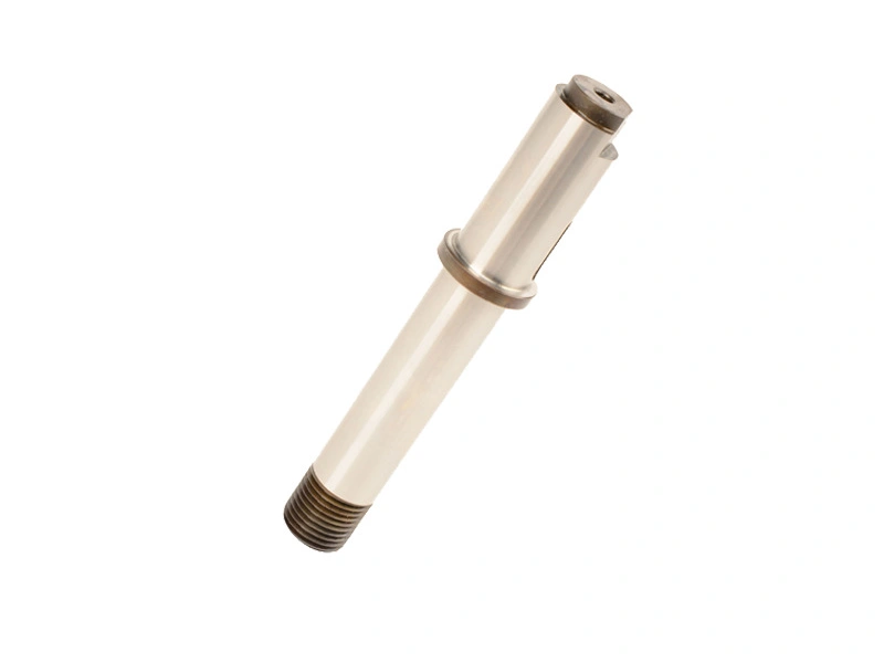
What Dimensional and Geometric Tolerances Are Most Critical in Oil and Gas Components?
The most critical dimensional and geometric tolerances in oil and gas components are the ones that control the pressure boundary, seal contact, guided clearance, thread engagement, port location, datum transfer, and rotating alignment. They commonly include bore and sealing diameters, thread requirements, roundness or cylindricity, flatness or profile, position, perpendicularity, and circular or total runout. No tolerance type or numeric value is universally critical. Buyers should rank characteristics from the assembly and failure analysis, then state the drawing framework, datum scheme, final condition, measurement method, and reporting coverage in the RFQ.
Reliable CNC machining must reproduce relationships, not only individual sizes. CNC turning can establish related axes, faces, grooves, and threads in controlled setups, while CNC grinding may support a justified final size, form, or texture requirement. Neither process guarantees a tolerance by name. Machine, material condition, workholding, tool or wheel behavior, unclamping, later processing, and inspection uncertainty all affect the result. Critical characteristics should be verified after the last operation that can change them.
1. Why Geometric Tolerances Matter So Much in Oil and Gas Parts
Geometric tolerances matter because a correct local size does not establish the form of a feature or its relationship to the assembled datums. A bore may pass diameter limits but be lobed, tapered, bent, or off-axis. A sealing face may be flat yet tilted relative to the bore that guides the seal. A port may meet position while an internal burr or wrong diameter still restricts flow. Each control has a defined scope, and acceptance requires all functionally necessary controls rather than one convenient measurement.
The drawing should invoke the applicable ASME Y14.5 or ISO GPS framework and use a datum reference system that represents assembly. The buyer and supplier must agree how simulators, material-boundary modifiers, free-state or restrained conditions, and coating state apply. If a tolerance is tighter than the measurement method can resolve with suitable uncertainty, the drawing creates an acceptance dispute instead of useful control. Review the characteristic plan before machining and identify method, setup, temperature, restraint, sample frequency, and actual-value reporting.
Critical Tolerance Type | Main Function in Oil and Gas Parts | Risk If Poorly Controlled |
|---|---|---|
Roundness or cylindricity | Controls circular or full-surface form independently of basic feature size | Local seal gaps, binding, unstable clearance, or uneven wear despite an acceptable diameter |
Axis or surface relationship | Uses position, runout, profile, or another specified control to relate functional features to datums | Eccentric contact, stem load, vibration, thread-to-seal offset, or premature wear |
True position | Locates feature axes or center planes within the stated datum and material-boundary conditions | Port overlap loss, fastener mismatch, thin wall, passage breakthrough, or assembly interference |
Flatness or profile | Controls a surface form or, with profile and datums, its form and relationship | Uneven compression, rocking, localized contact, gasket damage, or leakage |
Perpendicularity | Orients a face, axis, or center plane to the specified datum | Angular seating error, uneven preload, guide misalignment, or distorted assembly |
Circular or total runout | Controls rotating surface variation relative to a datum axis over a section or full surface | Dynamic seal variation, vibration, eccentric wear, or unstable rotating clearance |
2. Roundness Is Critical for Sealing Bores and Precision Diameters
Roundness is critical when circumferential contact or clearance must remain uniform, but roundness does not control diameter size, straightness, taper, axis location, or the full three-dimensional surface. A two-point size measurement can miss a lobed condition, and one circular trace can miss form change along a long bore. Cylindricity may be more suitable when the complete cylindrical surface matters. The design authority should choose the control from seal length, guide behavior, pressure deformation, and mating-part tolerance rather than a generic precision class.
Inspection must match the required form and feature access. A roundness instrument, suitable coordinate measurement strategy, or validated bore method may provide different coverage and uncertainty. The report should identify measurement sections, filtering or evaluation settings where relevant, temperature, restraint, and final material or coating state. Thin rings and sleeves can change shape when released from a chuck or fixture. Measure them in the specified free or restrained condition, and do not infer roundness from one diameter result or from machine spindle performance.
3. Concentricity and Coaxial Alignment Are Essential in Turned and Sealing Components
Coaxial functional alignment is often essential, but the word “concentricity” does not by itself define the best requirement. Depending on the drawing framework and function, position, circular runout, total runout, profile, or another control may communicate the needed relationship more directly. ASME Y14.5 editions do not all treat concentricity the same way. Procurement should not translate or replace the symbol informally. Ask the design authority which derived axis, surface, or rotating behavior must be controlled and to which datum system.
Controlled precision turning can reduce transfer error when bores, sealing lands, shoulders, and threads remain in one setup. Rechucking, reversing, heat treatment, grinding, or later milling can alter the relationship. The inspection setup must reproduce the specified datum and evaluate the defined control; indicating two convenient diameters does not necessarily prove an axis requirement. Buyers should request actual results for the critical relationship and verify it after all operations that can move, distort, or re-reference the feature.
4. True Position Is Often the Most Important Hole-Related Tolerance in Valve Bodies and Connectors
True position is often critical for ports, cross holes, threaded passages, fastener patterns, and guide bores because it controls feature location relative to the stated datums. It does not control feature size, form, surface damage, or remaining burrs. At maximum or least material condition, bonus tolerance and datum shift apply only as defined by the invoked drawing rules. A coordinate report that ignores modifiers or uses an unapproved alignment can produce a plausible number with the wrong acceptance boundary.
For intersecting passages, position affects overlap, minimum wall, breakthrough location, deburring access, and flow continuity. Review the basic dimensions, datum sequence, projected tolerance zone if used, thread or bore depth, and material-boundary condition together. The supplier should show how the setup transfers datums and how hidden intersections are verified after drilling and deburring. When functional gauging is used, define which collective boundary it proves and which individual actual values still require variable measurement.
Component Type | Most Critical Geometric Controls | Why They Matter |
|---|---|---|
Valve body | Port and guide position, bore form, seat profile, face orientation, wall and passage relationships | Controls shutoff alignment, flow continuity, sealing contact, deburring access, and pressure-boundary margin |
Connector or fitting | Thread size and form, thread-to-seal relationship, shoulder flatness or orientation, sealing diameter form | Controls engagement, preload, mating alignment, galling exposure, and leakage-barrier continuity |
Shaft or sleeve part | Diameter size, roundness or cylindricity, datum-axis relationship, runout, straightness, and texture | Controls guided clearance, dynamic seal behavior, rotation, load distribution, and wear rate |
5. Flatness Is Critical on Sealing Faces and Mounting Interfaces
Flatness is critical when one surface must contact a seal, gasket, shoulder, or mounting interface uniformly. Flatness controls a single surface without a datum; it does not control parallelism, perpendicularity, thickness, profile to another feature, surface texture, or assembled distortion. A face can pass flatness yet sit at the wrong angle to a guide bore. The drawing may need flatness plus orientation, or a datum-referenced profile, when both local contact and relationship matter.
Contact performance also depends on waviness, roughness parameter, lay, scratches, dents, edge condition, bolt pattern, stiffness, and assembly load. Milling, turning, grinding, lapping, coating, and handling leave different signatures. Define the required final state and protective handling. Inspection should sample sufficient area with a method that can separate form from texture. A blue-check or leak test may provide functional evidence under stated conditions, but it does not replace a required geometric report or validate every service condition.
6. Perpendicularity and Runout Protect Assembly Stability and Dynamic Reliability
Perpendicularity protects angular relationships between faces, axes, or center planes and a datum. It is important where a shoulder seats against a mating face, a bore guides a stem, or a threaded connection must load squarely. The tolerance zone and datum reference determine what is controlled. Face wobble observed during rotation may indicate an orientation or axis problem, but a single indicator reading does not automatically isolate perpendicularity from flatness, datum form, or setup error.
Runout controls surface variation during rotation about a datum axis. Circular runout evaluates individual sections, while total runout addresses the full surface within its defined scope. Neither term should be substituted for position, cylindricity, or balance without design review. Inspection depends on a suitable datum simulation, stable support, sufficient rotation, and controlled indicator or measurement-system error. Report the datum and surface tested. A machine-side check can guide the process, but final acceptance should use the authorized part setup and method.
7. Geometric Tolerances Directly Affect Both Assembly and Sealing
Geometric tolerances affect assembly and sealing through a shared stack of mating features, but a part can assemble without meeting the sealing requirement. Clearance may allow an off-axis stem to enter while creating uneven seal compression. Fasteners may pull a tilted interface together while distorting a bore. A thread may gauge successfully while its shoulder relationship creates false torque or poor contact. Buyers should evaluate the complete functional chain and avoid using successful hand assembly as final geometric acceptance.
Build a failure-control matrix that links each stack contributor to prevention, measurement, sampling, and reaction. Include mating-part tolerances, coating thickness, temperature, restraint, pressure deformation, and wear where they materially affect the result. The supplier should identify which characteristics are measured in process and which are released in final state. Any deviation or drawing interpretation that changes the stack requires written design-authority disposition rather than an undocumented shop-floor compromise.
Geometric Failure | Assembly Effect | Sealing or Reliability Effect |
|---|---|---|
Poor true position | Ports, guides, or fasteners approach the mating pattern with offset or reduced boundary clearance | Flow overlap loss, thin wall, side loading, distorted seals, or local pressure-boundary risk |
Weak flatness | Interface rocks or needs uneven clamp load to close visible gaps | Nonuniform compression, gasket damage, relaxation, or a persistent leakage path |
Bad axis relationship | Stem, sleeve, thread, shoulder, or seal enters with eccentric contact | Friction, galling, wear, unstable actuation, vibration, or asymmetric sealing load |
Excessive runout | Rotating or guided contact varies around the datum axis | Dynamic clearance change, seal pumping, vibration, heat, and shortened wear life |
8. Precision Turning and Grinding Often Provide the Best Control on These Features
CNC turning is often suitable for related cylindrical features, and CNC grinding can support a justified final form, size, or texture after prior operations. Process selection must follow material, stock allowance, geometry, access, heat-treatment state, workholding, and inspection requirements. Grinding can introduce burn, residual stress, cracks, or handling damage when poorly controlled. Turning can leave chuck distortion, deflection, thermal drift, tool marks, or burrs. Neither process name is acceptance evidence.
Broader CNC machining may be needed to connect turned or ground datums with ports, patterns, flats, and passages. The supplier should explain the route, datum transfers, stock left for finishing, distortion controls, and final verification. Buyers should request comparable material-condition-feature evidence, not a general statement about machine accuracy. Confirm the actual measurement method, uncertainty, sampling, and final-state report for each critical characteristic before approving the manufacturing plan.
9. Summary
The most critical dimensional and geometric tolerances are those that protect sealing, pressure-boundary margin, flow continuity, guided clearance, thread engagement, datum transfer, and rotating alignment. Roundness, cylindricity, flatness, profile, position, perpendicularity, and runout each have different scopes. “Concentricity” or “coaxial” language must be resolved within the invoked drawing framework rather than treated as a universal symbol or measurement. A tight number without functional justification and a capable measurement method does not improve reliability.
Qualify suppliers through precision machining, turning, and grinding evidence that matches the material condition, feature, datum, process sequence, and final state. The RFQ should include the released drawing and framework, mating interfaces, service conditions, critical-characteristic ranking, coating state, free or restrained inspection condition, actual-value coverage, sampling, method requirements, and acceptance authority. That package lets the buyer compare verifiable control plans instead of generic tolerance claims.



