What dimensional accuracy and surface finish can metal 3D printing achieve?
Metal laser powder bed fusion, including DMLS and SLM, often uses about ±0.1 mm or ±0.2% of nominal dimension, whichever is greater, for dimensional accuracy and Ra 10-25 μm for surface roughness as early planning bands on suitable as-built external features. These values are not drawing guarantees because alloy, build orientation, geometry, supports, thermal history, and inspection method change the result. Buyers should separate as-built zones from datums, bores, sealing faces, threads, and fatigue-sensitive surfaces that need a qualified machining or finishing route.
Dimensional Accuracy of As-Printed Parts
The dimensional accuracy of a metal 3D printed part describes how closely the measured part matches the drawing after printing, cooling, support removal, and required thermal treatment. For DMLS or SLM, ± 0.1 mm to ± 0.2%, whichever is greater, is a useful RFQ screening range for suitable external features, not a production tolerance promise. ISO/ASTM 52902:2023 defines benchmark test-piece geometries and measurements for assessing an additive system's geometric capability; it does not qualify a production part. Acceptance must reference the drawing datums and the part condition after the last operation that can move the feature.
Influencing Factors:
Process Parameters: Laser power, scan speed, hatch spacing, layer thickness, recoating stability, and chamber oxygen level affect melt-pool size, shrinkage, density, and edge definition.
Part Geometry: Thin walls, tall ribs, unsupported edges, overhangs, and heavy sections cool differently and can move after stress relief or support removal.
Material: Different alloys such as Aluminum 6061 and Inconel 718 have different thermal conductivity, melt behavior, oxidation sensitivity, residual-stress risk, and post-processing needs.
Post-Processing: Stress relief, solution aging, HIP, and other thermal routes such as heat treatment can shift dimensions, so final inspection should occur after the last operation that can move the part.
Comparison with Traditional Methods: As-printed accuracy is normally looser than CNC machining on accessible features. Metal printing is chosen for geometry and material efficiency first; conventional machining is still used when a drawing needs a tight bore, flat datum, sealing land, or controlled thread.
Achieving Precision Tolerances with Hybrid Manufacturing
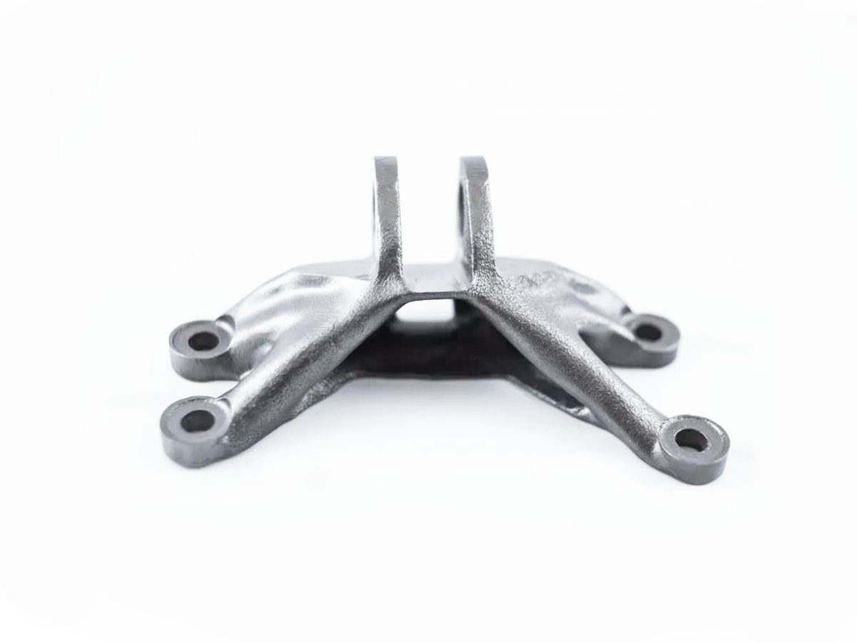
Precision metal 3D printed parts usually rely on a hybrid route: print the complex near-net shape, stabilize it thermally, then machine the surfaces that control fit, sealing, motion, or measurement. This route should be planned before printing because machining stock, datum pads, clamp areas, and tool access must exist in the model.
Secondary CNC Machining: Critical features are printed with allowance and finished through precision machining methods such as CNC milling or CNC turning. For a printed manifold with a machined flange and bores, stress relief should precede final datum cutting. If roughing releases residual stress, re-establish the datum and inspect the part after unclamping.
Realistic Tolerances: On selected machined features, ± 0.025 mm to ± 0.05 mm may be practical when the feature is accessible, the part is rigidly fixtured, enough stock remains, and the measuring method is suitable. For aerospace and medical devices, the inspection report should identify the final material state, datum alignment, measured feature, instrument, and acceptance rule rather than treating the full as-built body as equally precise.
Surface Finish of As-Printed Parts
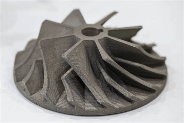
An as-printed DMLS surface is usually rougher than a machined surface because adhered particles, layer steps, melt-pool edges, and support contacts remain. Ra 10 - 25 μm (400 - 1000 μin) is a common screening range, but build angle, powder, alloy, scan strategy, and surface orientation can shift it. ISO 21920-2:2021 defines terms and parameters for profile-based surface texture; it does not make one Ra value a complete acceptance specification. Record the measurement location, direction, instrument and filter settings, and evaluation length with the result.
Causes of Roughness:
Partially Sintered Particles: Fine particles can adhere to melt-pool edges and down-facing surfaces, leaving a gritty texture that may trap contaminants or disturb flow.
"Stair-Stepping" Effect: Layer-by-layer building creates visible steps on curved and inclined surfaces, especially when the surface angle is shallow relative to the build plane.
Support Structure Artifacts: Support contact points can leave scars, pits, or local roughness after removal, so functional surfaces should avoid support contact when possible.
Functional Impact: As-printed roughness can be acceptable on non-contact structural surfaces, but it is risky for bearing surfaces, fluid seals, fatigue-loaded edges, sliding fits, and sanitary or cleanable passages. The buyer should identify which surfaces are cosmetic, functional, no-touch, or inspection-critical.
Improving Surface Finish Through Post-Processing
Post-processing can lower surface roughness, but no single method suits every surface. Access, roughness target, dimensional allowance, edge sensitivity, contamination risk, and internal-channel geometry determine the route. The ranges below are planning examples; qualify the selected process on a first article and measure the same specified surface before accepting production parts.
Abrasive Blasting: Sandblasting can clean loose particles and reduce peak roughness, with a planning range around Ra 4 - 8 μm on accessible surfaces. Media, pressure, masking, and inspection matter because aggressive blasting can round edges or alter small holes.
Vibratory Finishing: Tumbling can radius edges, deburr accessible features, and produce a smoother semi-matte surface, often around Ra 1 - 4 μm when geometry allows. It is less suitable for fragile walls, protected datums, or deep internal channels.
Abrasive Flow Machining (AFM): AFM can polish internal channels by pushing abrasive media through the passage. Define the allowed material removal, minimum passage, protected interfaces, and validation method. A borescope or CT check can find local restrictions; a flow test confirms functional change when flow is the requirement.
Electropolishing: Electropolishing can produce about Ra 0.2 - 0.8 μm on compatible, accessible surfaces under a qualified alloy, chemistry, current-density, and time window. Because it removes material, inspect small holes, sharp edges, and thin walls after processing; do not infer corrosion performance from Ra alone.
CNC Machining/Grinding: For critical planar, cylindrical, sealing, or bearing features, CNC grinding or final machining is usually the most controlled route. Values around Ra 0.4 μm or better may be specified on accessible features when stock, fixturing, tool path, and inspection support that requirement, similar to a controlled as-machined finish.
Summary of Achievable Specifications
Characteristic | As-Printed (DMLS) | With Post-Processing |
|---|---|---|
Dimensional Accuracy | ± 0.1 mm to ± 0.2% for suitable external features, depending on material, build direction, geometry, thermal stress, and support removal. | ± 0.025 mm to ± 0.05 mm on selected machined features when stock, fixture rigidity, tool access, and measurement method allow. |
Surface Finish (Ra) | 10 - 25 μm on many as-printed surfaces, with rougher values possible on down-facing or support-contact areas. | 0.2 - 4 μm depending on blasting, tumbling, electropolishing, grinding, machining, geometry access, and dimensional allowance. |
Engineering Guidelines for Design
Design for the Process: Avoid placing final tolerances on unsupported, downward-facing, powder-trapping, or inaccessible internal surfaces unless the post-processing and inspection route is defined before the build.
Specify Critical Features: Mark datums, sealing faces, bearing bores, threaded holes, fatigue-sensitive edges, and roughness-controlled surfaces. State the surface texture parameter, measurement location and direction, and whether acceptance occurs before or after finishing.
Consider the Entire Workflow: A high-precision metal printed part often needs 3D printing for the near-net body and CNC machining for final precision. The RFQ should identify alloy and condition, build-orientation constraints, as-built and post-processed zones, datum scheme, feature tolerances, surface measurement rule, sampling plan, and final acceptance state.