Quels paramètres sont essentiels pour la conception thermique des luminaires LED haute puissance ?
D’un point de vue ingénierie, une gestion thermique efficace dans les luminaires à LED haute puissance est non négociable pour garantir la longévité, la stabilité du flux lumineux et la constance de la couleur. Les paramètres essentiels forment une chaîne de résistances thermiques allant de la jonction de la LED jusqu’à l’environnement ambiant ; négliger un seul maillon de cette chaîne peut conduire à une dégradation catastrophique des performances.
La chaîne de résistance thermique : de la jonction à l’ambiance
Le cœur de la conception thermique réside dans la gestion du chemin de transfert de chaleur, quantifié par la résistance thermique (Rθ). La résistance totale du système, Rθ-JA (jonction à ambiance), est la somme de toutes les résistances en série. Les principaux paramètres incluent :
Rθ-JC (Jonction à boîtier) : C’est une propriété intrinsèque du composant LED, fournie par le fabricant. Une valeur plus faible indique un boîtier plus efficace pour transférer la chaleur du semi-conducteur vers son boîtier ou pad thermique.
Rθ-CS (Boîtier à dissipateur) : Cette résistance est dominée par le matériau d’interface thermique (TIM). Les paramètres essentiels du TIM comprennent sa conductivité thermique (W/m·K), son épaisseur et la présence de vides. Une application correcte garantissant une couche mince et uniforme est cruciale. L’utilisation de matériaux haute performance, similaires à ceux employés pour la gestion thermique dans l’électronique automobile, est souvent nécessaire.
Rθ-SA (Dissipateur à ambiance) : Il s’agit de la résistance du dissipateur thermique et de son interaction avec l’environnement. C’est le paramètre le plus déterminant au niveau du design.
Paramètres critiques du dissipateur et du système
Les performances du dissipateur thermique dépendent de son matériau, de sa géométrie et de la méthode de refroidissement. Les paramètres essentiels sont :
Conductivité thermique du matériau : Les alliages d’aluminium (par ex. aluminium 6061) sont standards grâce à leur bonne conductivité, leur usinabilité et leur coût modéré. Pour les applications extrêmes, le cuivre ou des composites spécialisés offrent de meilleures performances. Le choix du matériau implique souvent un compromis étudié à travers des traitements thermiques pour optimiser les propriétés.
Surface et géométrie des ailettes : La surface totale, la densité, la hauteur et l’épaisseur des ailettes influencent directement le transfert thermique par convection. Les conceptions sont souvent optimisées pour la convection naturelle ou forcée, impactant ainsi l’espacement entre les ailettes.
Méthode de refroidissement :
Convection naturelle : Repose sur le mouvement d’air par flottabilité. Les paramètres essentiels incluent l’orientation du luminaire et le dégagement nécessaire pour un flux d’air non obstrué.
Convection forcée : Utilise un ventilateur. Les paramètres clés sont le débit d’air (CFM ou m³/s), la pression statique et l’impédance aérodynamique du système.
Conditions limites opérationnelles et environnementales
La conception doit tenir compte des conditions réelles d’exploitation :
Température de jonction maximale (TJ-Max) : La température maximale absolue supportable par le semi-conducteur de la LED, généralement 150 °C. Une règle de conception courante consiste à maintenir la température de jonction à l’état stable en dessous de 110–120 °C pour assurer une longue durée de vie.
Température ambiante (TA) : Température maximale de l’air environnant dans lequel le luminaire fonctionne (ex. 40 °C, 50 °C ou plus dans les environnements industriels).
Puissance d’entrée et charge thermique : La chaleur à dissiper ne correspond pas à la puissance électrique totale, mais à la fraction non convertie en lumière. Pour les LED modernes, cela représente généralement 70–85 % de la puissance totale.
Considérations sur les matériaux et la fabrication
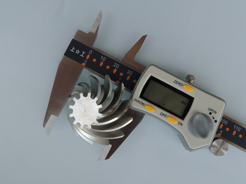
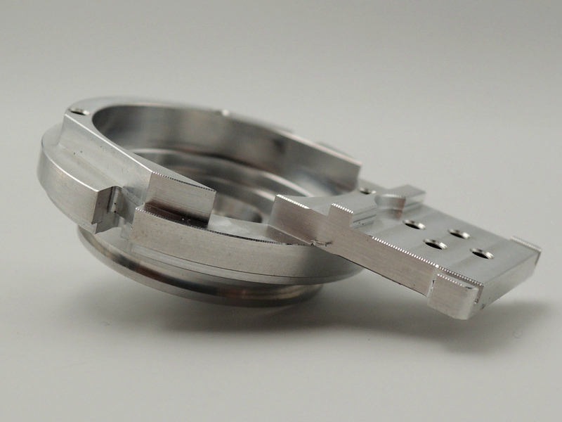
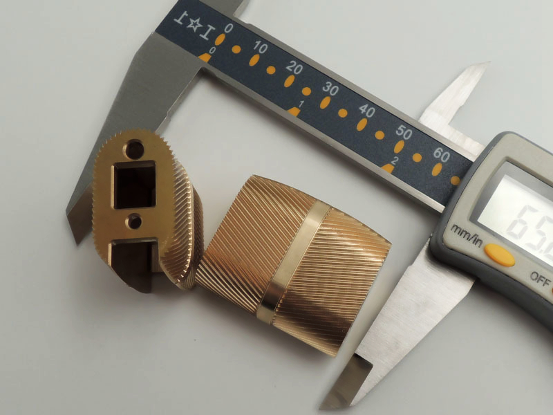
La réussite du design thermique dépend directement de la fabrication. L’usinage CNC permet la création de dissipateurs thermiques complexes et précis à partir de blocs massifs d’aluminium ou de cuivre, assurant d’excellents chemins thermiques. Pour la production en volume, le prototypage CNC et les procédés tels que l’usinage CNC de l’aluminium sont essentiels pour valider les performances thermiques avant la fabrication de série. De plus, l’anodisation de l’aluminium CNC peut améliorer l’émissivité de surface pour un meilleur refroidissement radiatif et offrir une protection environnementale.
Intégrer la conception thermique dans le cycle de vie du produit
La gestion thermique ne doit jamais être un ajout tardif. Elle doit être intégrée dès la conception initiale. L’analyse CFD (Computational Fluid Dynamics) est utilisée pour simuler les performances thermiques et optimiser le design avant la fabrication de prototypes physiques. Ces prototypes, pouvant être réalisés via le moulage rapide pour les boîtiers non structurels ou via l’usinage CNC de précision pour le dissipateur, sont ensuite testés en chambre climatique pour valider le modèle thermique sous diverses conditions ambiantes et charges électriques. Cela garantit que le produit final, qu’il s’agisse de produits grand public ou d’applications industrielles, atteigne ses objectifs de durée de vie et de performance.


