Sinker EDM for Sharp Internal Corners, Blind Cavities, and Complex Mold Features
Sinker EDM for Sharp Internal Corners, Blind Cavities, and Complex Mold Features
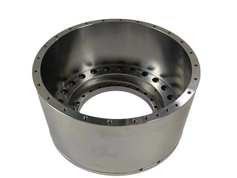
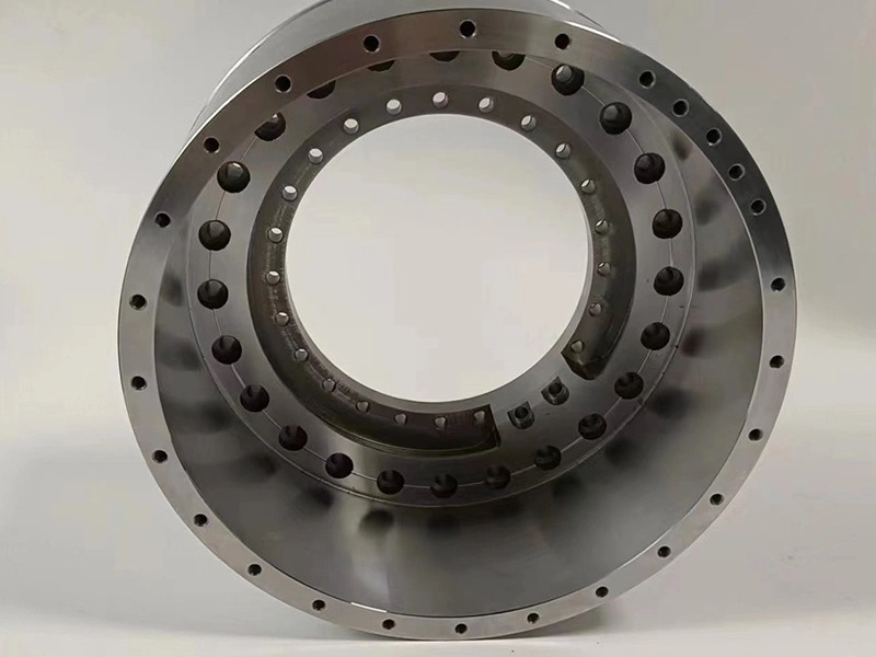
Sinker electrical discharge machining (EDM) forms blind cavities, non-through slots, and complex internal details in electrically conductive workpieces by reproducing a shaped electrode through controlled spark erosion. It is a practical route when a rotating cutter cannot enter the feature or would leave an unacceptable tool radius. A sinker EDM corner is still finite, however. Electrode geometry, discharge gap, electrode wear, flushing access, cavity depth, and the specified finish together determine the smallest stable internal radius. Buyers should therefore define the functional radius, cavity depth, datum relationship, surface condition, and inspection method instead of requesting an undefined "sharp" corner.
The process is commonly evaluated for hardened mold inserts, die components, tooling details, and other conductive parts with inaccessible geometry. Unlike wire EDM, which needs a continuous wire path through the workpiece, sinker EDM machining uses a formed electrode that advances into a blind feature. Low mechanical cutting force helps with delicate geometry, but it does not remove thermal, residual-stress, or handling risks. A useful route review must confirm electrode access, dielectric circulation, material and heat-treatment state, stock left by earlier operations, and the final condition in which the cavity will be measured. Electrode access includes more than a clear vertical approach. The holder must clear neighboring walls, the electrode must reach the lowest functional detail, and displaced dielectric fluid needs a path out of the cavity. A closed pocket without effective flushing can develop unstable discharges, debris marks, taper, or excessive wear. If a feature cannot be vented or inspected after the final pass, that limitation should be resolved in the drawing review rather than treated as an EDM setting problem.
When Sinker EDM Is Needed Instead of Milling
Sinker EDM is preferred over milling when the required conductive-metal feature is blind, internally formed, inaccessible to a rigid cutter, or limited by a cutter radius that conflicts with function. Milling remains the efficient first choice for accessible stock removal, open pockets, and features with acceptable radii. The decision changes when tool reach, neck clearance, chatter, deflection, or collision risk prevents a cutter from holding the required cavity geometry. Sinker EDM also becomes relevant after hardening, provided the drawing addresses the thermal surface left by the discharge process. The correct comparison is feature by feature, because one part can use milling for bulk removal and EDM only for the inaccessible finish geometry.
Machining Challenge | Sinker EDM Value |
|---|---|
Blind cavities | A formed electrode can enter a non-through cavity, but depth, venting, debris removal, and inspection access must be confirmed before release. |
Sharp internal corners | EDM can produce a smaller finite radius than many milling cutters. The drawing should state a maximum permitted radius rather than imply a zero-radius corner. |
Hardened steel | Electrical erosion is not governed by cutting hardness, although conductivity, heat-treatment distortion, recast requirements, and the final hardness state still affect the route. |
Deep narrow slots | EDM avoids a long rotating cutter, yet unstable flushing or electrode wear can create taper, undersize detail, and inconsistent depth in a narrow blind feature. |
Complex mold features | The electrode can transfer ribs, bosses, textures, and blended forms when its manufacture, overburn allowance, orientation, and datum pickup are controlled. |
Weak surrounding structures | Low cutting force reduces tool-load deflection, but thin walls can still move when residual stress is released or the fixture is removed. |
A robust route normally uses CNC milling to remove accessible bulk stock and establish reference surfaces before EDM. The handoff should state how much material remains in the cavity, which datums survive heat treatment, and whether the EDM setup locates from finished or provisional features. For a thin mold insert, rough milling can release stress before hardening, while final EDM can preserve an inaccessible corner. The buyer still needs evidence that the unclamped part holds cavity location and wall thickness. A process that measures only while the part remains in the EDM fixture can miss movement after release. Before EDM begins, remove burrs and trapped chips from pre-machined pockets because they can interfere with electrode seating and dielectric flow. A small allowance left for EDM should be uniform enough for the planned roughing conditions, yet the amount must be derived from the feature and electrode plan rather than copied from another cavity. When a ground surface will later locate a mating component, the route should also define whether EDM, polishing, or heat treatment occurs before that final reference is certified.
Sinker EDM vs Wire EDM vs CNC Milling
Choose sinker EDM for a blind formed cavity, wire EDM for a through profile with a valid wire path, milling for cutter-accessible geometry, and EDM hole drilling for a small deep hole. The feature boundary matters more than the shared EDM name. A wire cannot create a closed blind floor, while a formed sinker electrode is inefficient for many simple open profiles. Milling may still be preferable when its tool radius is acceptable and the surface must avoid an EDM recast layer. Buyers should divide a mixed part into features, identify the controlling acceptance requirement for each feature, and let the supplier propose a sequenced route without changing the drawing contract.
Process | Best-Suited Features |
|---|---|
CNC Milling | Open pockets, planes, steps, and accessible contours where cutter diameter, reach, and rigidity satisfy the corner, wall, and surface requirements. |
Wire EDM | Through profiles and narrow cut-through slots in conductive stock when start access, wire path, slug control, taper, and cut direction are defined. |
Sinker EDM | Blind cavities, formed internal details, deep non-through slots, and mold features where electrode access, dielectric flow, and finite corner radius are acceptable. |
EDM Hole Drilling | Small start holes, cooling holes, and deep flow passages whose diameter, breakthrough condition, taper, recast, and cleanliness have separate acceptance criteria. |
The RFQ should not force one process label onto every feature. It should instead identify blind versus through geometry, permissible corner radii, functional surfaces, material state, and prohibited process effects. The supplier can then separate roughing, heat treatment, grinding, milling, wire EDM, hole drilling, and sinker EDM into a controlled sequence. A route change after electrode manufacture can invalidate compensation and inspection planning, so any switch between these processes should require review of affected dimensions, surfaces, datums, and evidence before production continues.
Electrode Design and Machining Accuracy
A sinker EDM electrode is a compensated process tool, not a duplicate of the nominal cavity. Its dimensions account for the intended discharge gap, the direction of material removal, planned orbiting motion, wear, and the roughing or finishing stage. Copper and graphite are common electrode materials, but neither is universally superior. Selection depends on edge detail, removal rate, wear behavior, electrode machinability, cavity depth, surface target, and the workpiece material. The supplier should document which electrode controls each feature and how that electrode is oriented to the workpiece datums.
Roughing and finishing often need different electrodes or different compensated conditions. A roughing electrode removes most stock with a larger energetic gap, while a finishing electrode restores size, corner definition, and texture under lower-energy conditions. Electrode wear is rarely uniform: projecting ribs and corner details can lose material faster than broad faces. Deep cavities add debris and dielectric-flow effects that can destabilize discharges near the floor. Wear compensation, staged depth, electrode redressing or replacement, and controlled orbiting can manage those effects, but each choice changes the cavity envelope. The finished cavity must therefore be accepted from workpiece measurements, not inferred solely from the electrode drawing or machine coordinates.
Datum transfer is equally important. A cavity aligned to ground shutoff faces, dowel bores, or a molded-part reference needs a setup that preserves those relationships after earlier operations. The broader discipline associated with precision machining applies here: inspect the electrode, verify setup orientation, control dielectric condition, and measure the completed cavity in its specified final state. Consider a non-supplier-specific engineering scenario involving a hardened tool-steel insert with a deep blind rib cavity beside a thin wall. Rough milling establishes external datums, heat treatment occurs before finish EDM, and separate rough and finish electrodes address stock removal and corner detail. The release plan checks cavity depth and location from the final datums, examines wall movement after unclamping, verifies the defined surface condition, and records any electrode substitution. The buyer approves the route only when those results satisfy the drawing, not because the electrode nominally matches the CAD model. Electrode inspection is a separate control point. The fabricated electrode should be checked against the compensated design before it enters the workpiece, with particular attention to thin ribs, corner lands, and features that will wear early. The workpiece inspection plan then verifies the inverse cavity result. This distinction prevents an acceptable electrode measurement from being mistaken for proof of acceptable cavity dimensions. If orbiting is used to reach a sidewall or improve debris removal, the programmed path and the resulting cavity envelope must remain consistent with the released tolerance interpretation.
Materials and Parts Suitable for Sinker EDM
Sinker EDM requires an electrically conductive workpiece and is most useful when hardness, tool access, or internal form makes conventional cutting unsuitable. Hardened tool steels, conductive stainless steels, titanium alloys, nickel-based alloys, and some conductive carbide systems can be candidates. Grade names alone do not establish EDM behavior. Conductivity, heat-treatment condition, product form, carbide or inclusion structure, section thickness, and the permitted thermal surface all affect process stability and acceptance. Nonconductive ceramics and polymers are outside the normal sinker EDM mechanism unless a separately qualified conductive system is specified.
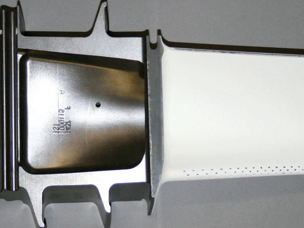
Mold inserts, dies, punches, medical tooling details, and aerospace or energy components may combine conventional machining with EDM-generated blind geometry. For high-temperature alloys, superalloy CNC machining can establish accessible features before EDM addresses an internal cavity. Heat treatment should be placed deliberately. EDM after hardening avoids cutting the final hardness with a rotating tool and allows correction after heat-treatment movement, but it leaves the EDM thermal surface late in the route. EDM before hardening exposes the cavity to subsequent scale, distortion, and dimensional change. Thin walls require another check because low process force does not prevent residual-stress release. The RFQ should identify material grade, product form, heat-treatment specification, supplied hardness evidence, and the process state required for final inspection.
Surface Integrity and Recast Layer Considerations
Sinker EDM removes material thermally, so the accepted surface must address texture, recast layer, possible microcracking, cleanliness, and any later polishing or grinding. Discharge energy, pulse control, dielectric condition, electrode material, debris evacuation, and the number of finish stages influence the resulting surface. A rough cavity can be dimensionally close yet unsuitable for a sealing, fatigue-sensitive, polished, or replicated mold surface. Conversely, a blanket demand for the finest EDM finish can add electrodes and machine time without improving a nonfunctional cavity. The drawing or purchase specification should distinguish dimensional surfaces, appearance surfaces, sealing regions, and areas that will receive secondary finishing.
Post-EDM polishing can change more than roughness. It can soften a sharp edge, enlarge a narrow rib space, change local draft, or remove stock unevenly from a deep cavity. Grinding is relevant only where wheel access and geometry permit; CNC grinding does not substitute for inaccessible cavity finishing. Cleaning must remove dielectric residue and loose debris without damaging fine details. Inspection should separate cavity size, depth, location, corner radius, taper or draft, surface texture, and recast acceptance. A coordinate measuring machine may verify accessible geometry, while optical methods, profilometry, replicas, sectioned qualification samples, or other agreed methods may be needed for recessed surfaces. The method, access, sampling plan, and acceptance state belong in the RFQ because no single instrument proves every requirement. For a mold cavity, specify whether a visual surface, a functional shutoff, or a replicated molded surface controls the finish decision. A polished test area cannot automatically represent a deeper rib or corner. The inspection record should identify the probe or optical access direction, the datum state, and any regions excluded because the instrument cannot reach them. When destructive metallography or a witness sample is the agreed recast check, its material condition and finishing parameters must represent the released operation. This keeps a surface-integrity claim tied to evidence rather than to a generic EDM finish description.
Surface Integrity Factor | Why It Matters |
|---|---|
Recast layer | Its permitted condition depends on fatigue, sealing, wear, polishing, and customer specifications; verify by an agreed method when it is functionally controlled. |
Heat-affected surface | High-energy or unstable discharges can increase thermal damage risk, so critical surfaces need qualified settings and evidence matched to the application. |
Discharge energy | Higher-energy roughing removes stock faster but normally leaves a coarser thermal surface and more finishing work than a lower-energy finish stage. |
Electrode material | Material selection affects machinability, edge retention, wear, debris behavior, and achievable texture under the selected workpiece and cavity conditions. |
Roughing vs finishing passes | Separate stages balance stock removal against size and texture; acceptance should be based on the final cavity after all specified stages. |
Post-EDM refinement | Polishing or accessible grinding may remove thermal surface and improve texture, but allowance, corner preservation, cleaning, and reinspection must be planned. |
Request a Sinker EDM Quote for Complex Features
A quote-ready sinker EDM package defines the cavity as an engineering contract rather than a picture of a sharp shape. Provide the controlled three-dimensional model and two-dimensional drawing, material grade and product form, heat-treatment state, cavity depth, minimum wall, draft or taper, maximum permitted corner radius, dimensional tolerances, datum scheme, surface texture, recast requirement, and final inspection state. Identify which surfaces seal, mold, slide, or carry cyclic stress. State whether polishing stock is intentional, whether electrode texture is functional, and whether cavity cleaning has a residue criterion. Quantity and project phase also matter because prototype electrodes, production electrode sets, replacement strategy, and record requirements can change the route without changing nominal geometry. State the allowable material removal after EDM if polishing, lapping, coating, or a later fit operation can affect cavity size. Identify any electrical, fluid, thermal, or molding function that makes a corner, floor, or surface more critical than surrounding geometry. This allows the route to concentrate verification on the feature that governs performance instead of treating every visible cavity surface as equally restrictive.
For complex conductive-metal features, the supplier should return an operation sequence, electrode plan, proposed gap and wear controls, flushing or venting approach, inspection method, and any drawing conflicts before work begins. The existing sinker EDM machining scope can be coordinated with the linked one-stop CNC machining service only after each handoff and acceptance state is explicit. The buyer should compare proposals by cavity risk, evidence, and change control rather than by an unsupported promise of zero-radius corners. Require approval before electrode material, electrode count, heat-treatment sequence, polishing allowance, datum strategy, inspection method, or recast-control route changes. That discipline keeps the formed cavity, surrounding wall, and final surface tied to the released design.
FAQ
What information is needed to quote a Wire EDM or Sinker EDM project?
How small can EDM hole drilling go for start holes, cooling holes, and hard-metal features?
Can EDM machine sharp internal corners and blind cavities after heat treatment?
What surface and inspection requirements should be specified for EDM machined parts?