EDM Small Hole Drilling for Cooling Holes, Start Holes, and Hard-Metal Features
EDM Small Hole Drilling for Cooling Holes, Start Holes, and Hard-Metal Features
EDM small hole drilling makes narrow holes in electrically conductive parts by controlled spark erosion through a tubular electrode and dielectric flushing. It is a practical route for cooling holes, wire-cutting start holes, and features in hardened metal when a rotating drill would face rapid wear, deflection, or an unstable entry. The process does not remove every constraint: electrode access, material conductivity, entry geometry, depth-to-diameter ratio, flushing, breakthrough condition, and final inspection still determine whether EDM hole drilling services fit the part. Buyers should therefore specify the finished hole function and acceptance state, not only a nominal diameter.
EDM small hole drilling is most useful when the feature is part of a defined manufacturing route. A start hole must let the wire pass through without entering a protected finished surface. A cooling or fluid hole must be open, clean, and suitable for the required flow condition. A hole in heat-treated steel, superalloy, or conductive hard metal must preserve nearby walls and datums while meeting the drawing after all planned downstream operations. Nonconductive materials are outside the EDM mechanism, and a blind feature may need sinker EDM or another process if controlled bottom geometry matters. The sourcing decision must connect feature function, process access, risk, and verification.
What Makes EDM Hole Drilling Different From CNC Drilling?
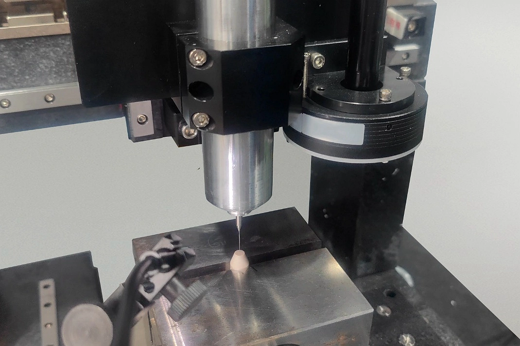
EDM hole drilling differs from CNC drilling because electrical discharges erode conductive material instead of a cutting edge shearing it under thrust. A tubular electrode approaches the part while dielectric fluid passes through the tube, carries debris from the gap, and helps keep discharges stable. This removes conventional cutting-force and edge-wear limits, but introduces electrode wear, spark-gap, flushing, thermal surface, and breakthrough controls. CNC drilling remains preferable when a standard drill can produce the required hole efficiently, especially where threads, controlled drill-point geometry, or a conventional reamed finish are needed. Buyers should compare the finished requirement and total route rather than choosing EDM only because the material is hard.
Comparison Item | EDM Small Hole Drilling | CNC Drilling |
|---|---|---|
Material removal method | Controlled discharges erode conductive material around a tubular electrode; dielectric flow removes debris from the working gap | A rotating cutting edge shears material under axial feed and produces chips that must leave the flutes |
Best-suited materials | Electrically conductive hardened steels, superalloys, and conductive hard metals where tool wear or thrust creates risk | Machinable metals where tool geometry, coolant access, speed, feed, and chip evacuation can be controlled |
Tool force | No conventional drilling thrust, but spark-gap stability, electrode wear, and local thermal effects still require control | Thrust, torque, drill runout, cutting-edge wear, and part support can affect deflection and breakout |
Small-hole capability | Useful for narrow, deep conductive features when a matched electrode, access, flushing path, and inspection method are feasible | Often efficient for accessible holes, but risk rises as drill stiffness, chip evacuation, runout, and edge strength become limiting |
Curved or angled entry | Can avoid drill skating, although fixture orientation and asymmetric electrode wear must be validated at the real entry angle | May require a spot face, pilot strategy, rigid support, or a revised approach to control slip and drill deflection |
Typical follow-up use | Wire EDM start holes, cooling and vent passages, or conductive hard-metal features followed by cleaning and functional inspection | Standard assembly, tap-drill, counterbore, and general production holes that may be reamed, threaded, or deburred later |
EDM does not replace CNC drilling whenever the drawing shows a small or hardened-material hole. Mechanical drilling can offer a cleaner route for a short accessible hole, a threaded feature, or a bore intended for reaming. EDM becomes stronger when drill stiffness, edge wear, cutting force, or the entry surface would make the mechanical route unstable. A sound supplier comparison asks for the proposed sequence, planned electrode and flushing concept, expected exit condition, inspection access, and any secondary cleaning or surface-integrity step. That route-level evidence is more useful than an unsupported minimum-diameter claim. For a repeated hole pattern, the comparison should also address electrode-change criteria, indexing strategy, dielectric monitoring, and the reaction to blocked or partial breakthrough. These controls determine whether the first acceptable hole remains representative of later holes. The buyer should define whether process drift triggers added inspection, setup correction, or segregation of affected parts.
Typical EDM Small Hole Applications
EDM small hole drilling serves different functions, and each function creates a different acceptance decision. A wire EDM start hole must break through and provide enough clearance for threading while remaining inside scrap stock or another approved area. A cooling or fluid hole must preserve its effective flow path after debris removal and final cleaning. A vent hole may be judged by openness and location, while a hard-metal feature may place greater emphasis on entry condition, wall integrity, and downstream surface requirements. Turbine-style cooling features, mold vents, hardened-tooling passages, conductive nozzle or fluid holes, and access holes for later profile cutting can all be candidates. The shared requirement is electrical conductivity, not a specific industry label.
An engineering scenario illustrates the route choice without implying a supplier-specific customer case. Consider a heat-treated steel insert that needs a through start hole on an angled surface before an internal window is wire cut. A mechanical drill could skate at entry or deflect toward the unsupported side. An EDM route can fixture the qualified datum, establish the electrode approach, confirm breakthrough, clean the passage, and then thread the wire. The buyer should verify start-hole position before profile cutting and inspect the finished window after stress release. If the start hole would intrude into the finished contour or leave too little wall, the correct decision may be to move it into sacrificial stock, change the process sequence, or use a different entry feature rather than force the EDM plan.
Technical Data Buyers Should Confirm
Buyers should confirm the hole contract, material state, access, and acceptance method before an EDM small-hole quote is treated as comparable. Nominal diameter alone does not define the job. The drawing or model should identify through versus blind intent, depth, location from functional datums, entry and exit surfaces, approach angle, adjacent-wall condition, and whether intersecting passages are expected. The material specification must include grade and the state in which EDM occurs, including heat treatment, coating, or stock condition where relevant. These inputs control electrode choice, fixture orientation, available dielectric flow, and the risk of taper, entry flare, blocked breakthrough, or wall damage.
Electrode diameter and wear influence the produced hole, but they are not direct promises of finished size. Discharge settings, gap behavior, material conductivity, depth, flushing, and entry geometry change the result. Deep or angled holes need a defined approach and a feasible path for debris to leave the gap. Intersecting holes can change flushing abruptly when breakthrough occurs, while a thin wall can experience local overburn or edge damage if the discharge becomes unstable. Recast and thermally affected surface material may be acceptable for a noncritical start hole but restricted on a fatigue, sealing, or controlled-flow surface. The RFQ should state the functional limit and required evidence instead of assuming one finish rule suits every hole.
EDM small-hole capability must be qualified against the actual part rather than a universal sub-millimeter range. Equipment configuration, tubular-electrode availability, workpiece conductivity, depth-to-diameter ratio, entry angle, flushing path, and measurement access all set practical boundaries. Hole count also changes the plan because electrode consumption, indexing, debris control, and inspection effort accumulate across a pattern. For development work, a representative coupon or first article can validate the route if its material state, entry condition, depth, and flushing resemble the production feature. A coupon with easier access or different heat treatment cannot establish the finished-part result by itself. The validation record should capture the electrode specification, setup orientation, dielectric condition, entry and exit observations, hole measurements, cleaning state, and disposition of any unstable cycle. If production parts use several approach angles or depths, the validation should cover the worst credible combination rather than only the easiest hole. Buyers should also agree which changes require revalidation, especially a new material condition, electrode source, setup, flushing route, or inspection method.
Technical Parameter | Why It Matters |
|---|---|
Hole diameter | Defines the finished functional requirement; confirm tolerance and the measuring method rather than inferring size from electrode diameter |
Hole depth | Sets the depth-to-diameter challenge and affects electrode wear, debris evacuation, taper risk, cycle stability, and inspection access |
Entry surface | Curvature, angle, coating, and local wall support govern fixture orientation, start stability, entry flare, and validation needs |
Material hardness | Hardness does not prevent EDM, but grade, conductivity, heat-treatment state, and microstructure still affect discharge behavior and acceptance |
Hole straightness | Deep and angled passages can develop taper or drift; define the datum, evaluation length, and accessible verification method |
Recast layer | Surface-integrity limits depend on fatigue, sealing, flow, and downstream finishing requirements; state the permitted condition and evidence |
Surface finish | Texture can affect flow or cleaning, but the specification must identify the relevant surface, method, cutoff, and final process state |
Quantity | Hole count and pattern size affect electrode use, indexing, debris management, sampling, traceability, and total route cost |
EDM Drilling for Superalloy and Hardened Steel Parts
EDM small hole drilling is often selected for conductive superalloys, heat-treated steels, and conductive hard metals because electrical erosion is not governed by cutting-edge hardness in the same way as mechanical drilling. Materials such as Inconel, Hastelloy, and Stellite can accelerate drill wear and make chip evacuation difficult at small diameters. Hardened tooling can create similar risk when the hole is added after heat treatment. EDM avoids drill thrust and conventional edge failure, but the supplier must still control conductivity-dependent settings, electrode wear, dielectric condition, debris evacuation, and the thermal surface produced by each discharge. Material hardness alone is therefore not enough to approve the route.
Process sequence matters as much as material family. Drilling before heat treatment may simplify hole making but can allow later distortion, scale, coating, or stock removal to change the final feature. Drilling after heat treatment can preserve the final datum relationship, yet may place the EDM surface closer to the released condition and require specific recast or cleaning controls. Cooling and vent passages that intersect other holes need a planned breakthrough response because dielectric flow and discharge stability change at intersection. Start holes must connect cleanly to the later wire path. Projects that combine larger machined geometry with difficult alloys may use superalloy CNC machining, while corrosion-resistant fluid features may involve stainless steel CNC machining. The buyer should require one controlled process map covering datum transfer, heat-treatment state, EDM, cleaning, downstream cutting, final inspection, and deviation approval.
Inspection for EDM Small Holes
Inspection for EDM small holes should prove the feature's stated function in its final acceptance state. Diameter, location, depth, straightness, taper, entry and exit condition, openness, recast, cleanliness, or flow may matter, but not every method can verify every characteristic. A pin or plug can confirm accessible size acceptance without proving the full bore is straight. Optical inspection can document an entry or exit surface without measuring a hidden passage. Coordinate measurement can relate accessible features to datums but may not reach a deep narrow bore. Buyers should define each characteristic, datum, method, sampling rule, and final processing state before comparing inspection plans.
The inspection sequence should follow the manufacturing risk. First-article evidence can confirm setup, position, breakthrough, and the proposed measuring method before a full hole pattern is produced. Cleaning must occur before an openness or flow decision because loose debris can create a false failure or pass. A flow test can assess the assembled function of a cooling or fluid path, but it does not by itself identify diameter, taper, or surface-integrity cause. Recast review may require a qualified visual, metallographic, or other agreed method depending on the specification. Broader datum and acceptance planning can follow quality control in CNC machining when EDM is one stage within precision machining. Inspection records should link the accepted result to material state, machine route, electrode lot or controlled tooling record where required, and approved deviations. The selected measurement system must also resolve the stated tolerance at the actual feature size and access condition. Gauge calibration alone does not make an inaccessible characteristic measurable. A correlation study may be needed when development uses sectioning or computed imaging but production relies on gauges, optical methods, or flow. The control plan should identify how disagreement is resolved, who can authorize alternative evidence, and whether destructive validation applies to a coupon, a first article, or a sampled production part.
Inspection Item | Typical Purpose |
|---|---|
Pin-gauge inspection | Confirms accessible acceptance size under a stated gauge class and force; it does not establish full-depth straightness |
Optical inspection | Documents entry, exit, edge, and visible surface condition when magnification, lighting, and acceptance criteria are defined |
Hole position inspection | Relates the feature to specified functional datums and must identify whether entry, exit, or an evaluated axis controls acceptance |
Depth inspection | Confirms a blind-depth target or breakthrough condition with a method that can reach the feature without damaging it |
CMM for hole location | Supports datum-based location where probe access and feature size permit; inaccessible bore geometry needs another agreed method |
Burr / recast review | Checks visible edge and thermal-surface requirements in the specified final state, including any approved secondary removal process |
Flow test if required | Verifies a defined functional passage after cleaning under agreed fluid, pressure, temperature, fixture, and acceptance conditions |
Submit an EDM Hole Drilling RFQ
An EDM hole drilling RFQ should define the feature and its place in the process route. Provide the controlled drawing and model revision, material grade, conductivity-relevant material condition, heat treatment, and the state in which the hole is produced. Identify each hole's diameter and tolerance, depth or breakthrough intent, location datums, entry and exit surfaces, approach angle, adjacent thin walls, intersections, quantity per part, part quantity, and whether the feature is a cooling path, vent, fluid passage, or wire EDM start hole. State any prohibited start-hole witness, recast, edge, contamination, or surface condition. Include the required inspection method, first-article or sampling evidence, flow or cleanliness test conditions, record retention, downstream processes, and change-approval rule.
Buyers should select EDM when the qualified route controls a conductive hard-material feature more credibly than mechanical drilling, not merely because the nominal hole is small. A complete supplier response should identify the proposed electrode and flushing approach, fixture and datum transfer, process stage, breakthrough control, cleaning, inspection access, secondary operations, and assumptions that still require validation through EDM hole drilling services. Compare that response with the CNC, sinker EDM, laser, or design-change alternatives that are technically available. Release production only after representative first-article evidence confirms the finished hole contract, and require approval before changes to material state, electrode route, datum strategy, cleaning, inspection, or acceptance method.
FAQ
What information is needed to quote a Wire EDM or Sinker EDM project?
How small can EDM hole drilling go for start holes, cooling holes, and hard-metal features?
Can EDM machine sharp internal corners and blind cavities after heat treatment?
What surface and inspection requirements should be specified for EDM machined parts?