Milled Metal Parts: Datum Strategy, Feature Access, and Cost Control
Milled Metal Parts: Datum Strategy, Feature Access, and Cost Control
Milled metal parts are easier to release when the datum scheme, feature access, material condition, machining route, inspection method, and commercial scope are decided together. A buyer can reduce avoidable rework by identifying the interfaces that locate, seal, fasten, or guide the part before asking for a price. The drawing should connect each critical feature to a datum reference, a measurable acceptance rule, and a record tied to the part revision and lot.
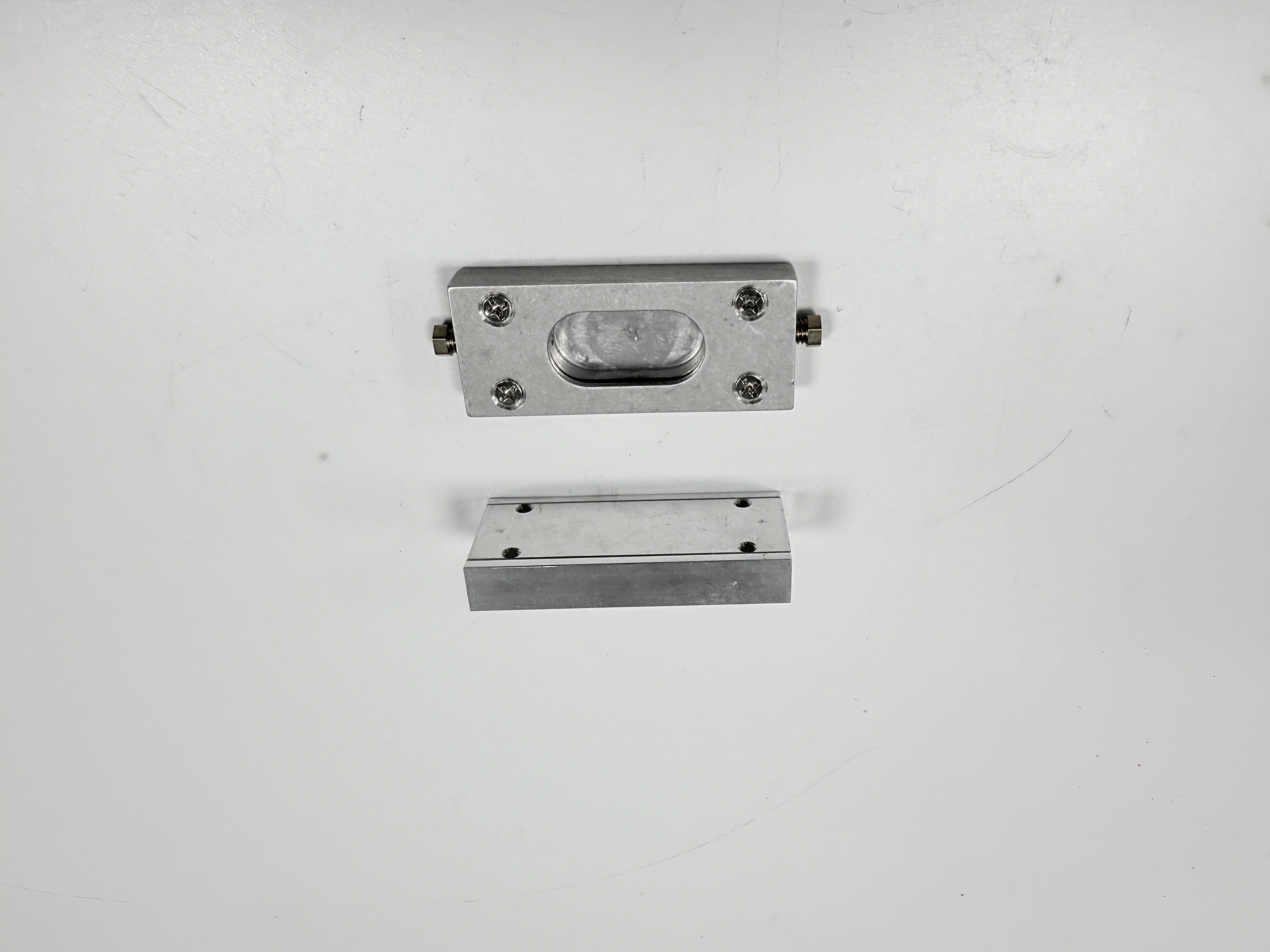
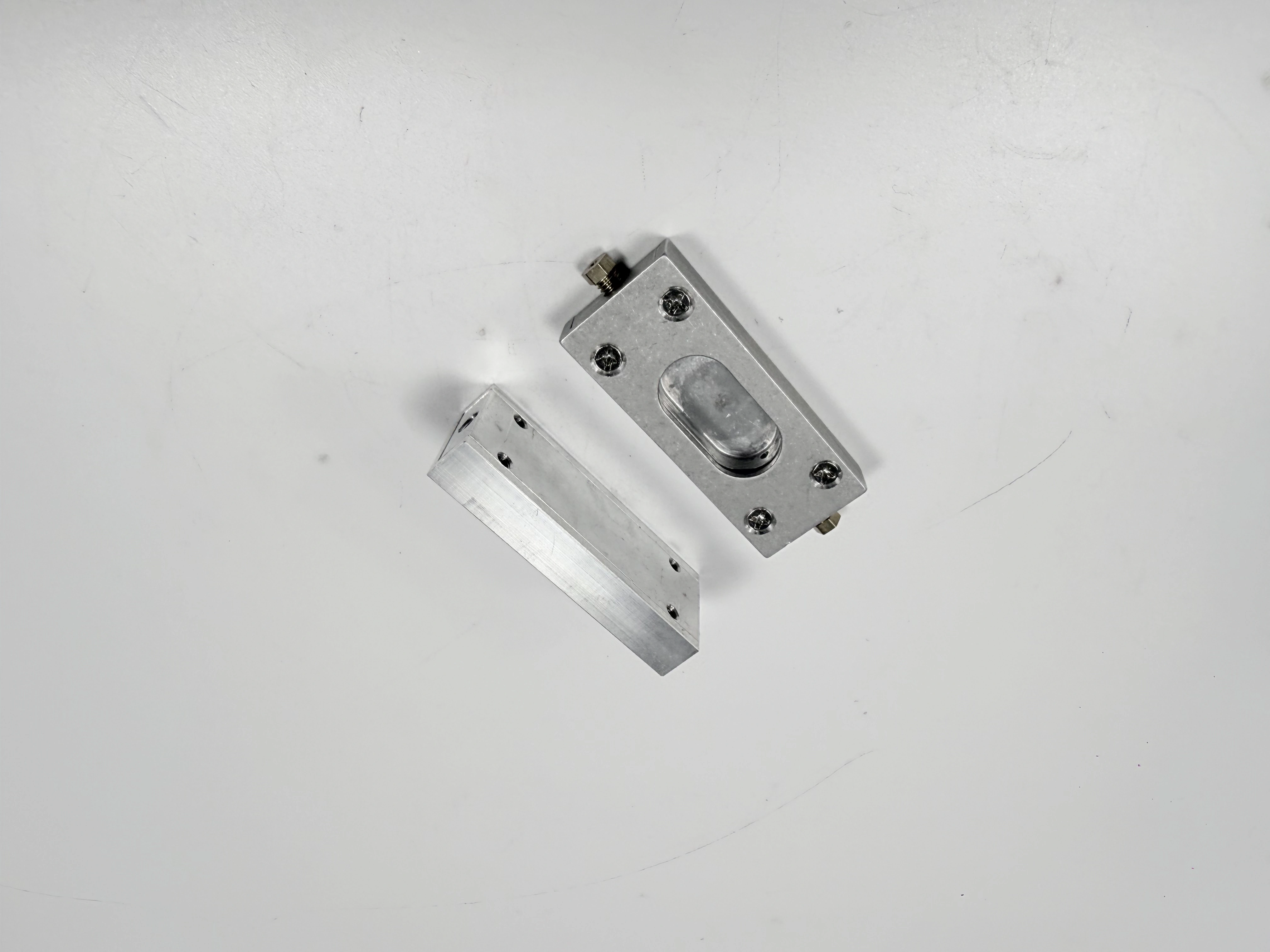
The paired images show one rectangular machined block and a separate upper piece. Visible details include an oval raised feature, a rectangular base, four apparent fastener locations, side hardware, and machined surface marks. Those observations support a discussion of datum access, split-part interfaces, and inspection planning. They do not establish the alloy, heat treatment, hardness, coating, tolerance, sealing duty, or intended industry. Those facts belong in the controlled drawing, material documentation, process records, and measured results.
Define the Decision Before Choosing a Route
The useful question is not simply whether a shop can mill a block. The decision is whether the proposed route can preserve the interfaces that matter, expose every required feature to a suitable tool and probe, and produce evidence that the receiving team can interpret. Start by writing the part function in engineering terms: a mounting interface may need positional control, a cover seat may need flatness and sealing behavior, a bore may need axis and size control, and a threaded hole may need both thread form and location. Separate those outcomes before discussing machine size or hourly rate.
For a first review, mark the primary assembly faces, secondary locating faces, hole patterns, pockets, bosses, threads, thin walls, and cosmetic zones. Record what touches another part and what can tolerate a small visual or dimensional variation. This turns a generic CNC machining service review into a feature-by-feature decision. It also prevents a supplier from treating every dimension as equally important or from hiding a difficult measurement inside a broad general tolerance.
Separate Function From Appearance
A clean-looking milled face can still have an incorrect orientation, and a hole that accepts a fastener can still miss the intended pattern. Classify each requirement as size, location, orientation, form, surface condition, or functional fit. Note the consequence if that characteristic drifts. This classification determines the datum frame, tool access, inspection method, and reaction plan. It also keeps the cost discussion honest: a feature that requires a controlled setup and a unit-linked measurement should not be priced like a non-functional cosmetic edge.
Build a Datum Strategy That Survives Setups
Datum selection should follow the way the part locates in its assembly, not the first flat face that is convenient to clamp. Choose a primary datum that constrains the largest functional motion, then add secondary and tertiary references that control rotation and remaining translation. Explain the relationship between the datum features and the hole patterns, bosses, cover seat, or bore axis. When the machining route needs more than one setup, identify how the datum frame is transferred and which shared feature verifies that transfer.
Do not replace a functional datum with a stock edge simply because it is easy to touch with a probe. Stock edges can change after roughing, and an edge that is square to the raw material may not be square to the finished interface. The drawing should state whether a datum is a surface, a derived axis, a center plane, or a pattern. The inspection report should use the same definition so a programmer, inspector, and buyer are evaluating the same geometry.
Control Datum Transfer Between Operations
When a block is flipped, rotated, or separated from a fixture, record the locating contacts, support points, clamp direction, and orientation used for each operation. A shared bore, reamed reference, or controlled external feature can provide a transfer check when it is accessible and stable. If no common reference survives both operations, the route needs an approved alternative such as a qualified fixture, a probing routine, or a measurement alignment that is defined in the drawing. “Same zero” is not evidence unless the physical reference and measurement method are recorded.
For parts with a removable cover or a two-piece interface, a datum plan should also state whether each piece is inspected alone, assembled, or both. Checking the base alone may miss a mismatch that appears only when the cover is installed. Checking the assembly alone may hide which piece caused the error. A clear split between component-level and assembly-level characteristics lets the buyer pay for the measurement that protects function rather than for an undefined inspection bundle.
| Datum question | Useful record | Failure prevented |
|---|---|---|
| What locates the assembly? | Primary interface and datum definition | A convenient but non-functional clamp face controls the part |
| How is rotation constrained? | Secondary datum and pattern relationship | Hole pattern direction changes after a flip |
| What survives a second setup? | Transfer feature and measured check | Features from separate operations lose their relationship |
| When is the pair checked? | Component and assembled acceptance states | A cover or base passes alone but fails at assembly |
Plan Feature Access Before Programming
Feature access is a geometric constraint, not a programming preference. Review tool diameter, holder clearance, spindle approach, probe reach, corner radius, chip evacuation, and the ability to support the workpiece without masking the characteristic. Deep pockets, narrow slots, recessed faces, and features under a cover may require a different cutter, a fourth-axis orientation, a second setup, or an approved inspection alternative. A route that reaches the feature but cannot measure it in the required state is incomplete.
Map access for roughing, finishing, deburring, and inspection separately. A tool may remove stock from a cavity while a finishing cutter cannot reach the last wall. A probe may touch an exposed face while a stylus cannot reach the bottom of a narrow pocket. Record the blocked region, the proposed method, and the evidence that will be returned. If a feature is functionally important but inaccessible to the planned method, escalate before cutting rather than accepting an undocumented substitute.
The CNC machining prototyping workflow can be useful for exposing access issues early, but a prototype route is not automatically a production route. The buyer should ask which setup assumptions remain valid at the intended quantity, which fixture elements change, and how the inspection plan will be repeated. A short prototype cycle is valuable only when it produces decisions that survive the production handoff.
Support Thin, Split, and Distortion-Prone Features
Thin walls, unsupported lips, and separated cover pieces can move when clamps are released. Define the support condition during roughing, finishing, and measurement. If a cover is inspected while resting on a surface that is not its assembly datum, note the alignment and contact points. Do not assume that a visually flat piece remains flat after unclamping or after a temperature change. The inspection record should identify the state in which the result was obtained.
Choose Material, Stock, and Condition Explicitly
A milled metal part begins with a material and condition that the drawing controls. State the alloy or grade, temper or heat-treatment condition, stock form, required certification, and any restrictions on substitutions. Add the rough-stock envelope and the allowance needed to clean up datum faces, pockets, and cosmetic surfaces. If the part will be anodized, plated, painted, or otherwise processed, specify which features are masked and which dimensions are checked after processing.
The visible silver appearance of the pictured parts cannot identify aluminum, stainless steel, or another alloy. The same visual finish can result from different materials and machining states. Use a controlled aluminum machining reference or a stainless-steel machining reference only after the drawing confirms the applicable material. For higher-strength requirements, a titanium material route brings different cutting, burr, heat, and inspection considerations; it should not be inferred from a photograph.
Match Allowance to the Route
Allowance is the stock left for a later operation, not a universal number. It depends on raw-material condition, workholding, expected distortion, heat treatment, coating, tool access, and the tolerance that remains after each step. Excess stock can increase cutting time, heat, and distortion; insufficient stock can leave a datum or cosmetic face below size after cleanup. The process plan should explain where allowance is consumed and where a final-state measurement is required.
For conductive copper or brass parts, a copper machining reference or brass machining reference may inform tool and burr questions, but only the specified grade controls acceptance. For ferrous parts, a carbon-steel route may alter chip control, coolant, corrosion protection, and inspection timing. The supplier should state assumptions instead of silently substituting a familiar stock condition.
Select a Sequence That Protects the Interfaces
Roughing, stress relief, semi-finishing, finishing, deburring, and outside processing should be ordered around the features that establish the datum frame. Rough material removal can release stress; a subsequent finish pass may be needed after the part stabilizes. Finish a robust reference early enough to locate later operations, but do not finish a surface that will be clamped in a way that can damage it. The sequence should also leave access for chips, burr removal, probing, and visual review.
Decide whether turning, boring, grinding, or a secondary process is required instead of forcing every characteristic into a single milling setup. A cylindrical feature may be better controlled by a CNC turning route when its function is rotational, while a deep or aligned bore may call for precision boring support. A surface or form requirement that depends on a stable finishing method may need precision grinding. These are route decisions, not claims that one process is universally superior.
Control Burrs and Surface State
Deburring should identify which edges may be broken, which edges must remain sharp, and how burr removal is verified. A visual check can find a hanging burr but cannot establish a numerical edge break unless the drawing defines a method. Surface appearance should be separated from roughness, waviness, and form. If a final finish is required, state the measurement method and the state of the part when it is measured. The as-machined finish guidance can frame that discussion without replacing the drawing requirement.
Outside processes can change dimensions, edges, color, or contamination state. If a coating or paint is specified, use a powder-coating process reference to identify masking and post-process inspection questions. Do not use a coating appearance as proof of thickness, adhesion, or durability. The acceptance record should show which characteristics were measured before the outside process and which were checked again after it.
Control Cost With a Comparable Scope
Cost control starts when every quote uses the same technical scope. Normalize material grade and condition, raw-stock size, number of setups, fixture ownership, programming assumptions, tooling, deburring, cleaning, outside processing, inspection, packaging, freight basis, quantity, and milestones. A quote that excludes a fixture or reports only the machining cycle can look inexpensive while transferring work to engineering, inspection, or receiving. Ask each bidder to list assumptions and exclusions in the same order.
Separate one-time and recurring costs. A fixture, soft-jaw set, probing routine, first-article inspection, or process qualification may be non-recurring; material, cutting time, outside processing, inspection per lot, packaging, and freight recur with quantity. For early work, low-volume manufacturing scope can be compared with a production route only when the change in fixture, inspection, and documentation is visible. For repeat demand, a mass-production planning reference can help frame capacity and control questions, but it does not prove a supplier's capacity for this part.
| Quote line | Normalize before comparison | Question to resolve |
|---|---|---|
| Material | Grade, condition, stock and certificate | Is the quoted stock the same acceptance basis? |
| Setup and fixture | Operations, locating scheme and ownership | Does the price include repeatable datum transfer? |
| Inspection | CTQs, sampling, method and records | Which results are unit-linked and which are sampled? |
| Outside process | Processor, masking and final-state checks | Are post-process dimensions included? |
| Logistics | Quantity, packaging, labels and freight basis | Are delivery records and protection requirements equal? |
Design Inspection Evidence Around CTQs
Inspection should answer whether each critical-to-quality feature meets its defined rule in a known state. For every CTQ, request nominal or acceptance limit, actual result, units, datum frame, method or instrument, measurement condition, inspected unit, and record revision. Distinguish 100% checks from samples. A sample can show a lot trend, but it cannot silently cover a feature that the drawing or quality agreement requires on every unit.
Match the method to the characteristic. A caliper may screen an accessible size; it does not establish a hole pattern, axis, or profile. A CMM result may describe location and form in a stated alignment; it does not prove a sealing test unless the functional test is also defined. A thread gauge can confirm a fit condition while leaving location or perpendicularity unresolved. The inspection plan should state what the method proves and what it cannot prove.
Tie Results to Lot and Revision
Traceability should connect the finished unit to the drawing revision, material lot, process route, outside processor, inspection record, deviation, label, and shipment. If a result changes after rework, retain the original and final state with the disposition authority. A certificate can support material identity, but it does not replace finished-part measurements. A photograph can show that a visible feature exists, but it does not replace a controlled result.
For a two-piece block and cover, record whether the cover is measured against its own datums, against the base, or in an assembled state. Note the fastener or locating condition used during any functional check. If a discrepancy appears, contain the affected lot, identify the operation or state that could have caused it, and decide whether expanded inspection, rework, replacement, or an approved deviation is appropriate. Do not close the issue with a general statement that the part was “checked.”
Write One Complete RFQ Scope
The RFQ should convert the design intent into inputs that a supplier can price and an inspector can verify. Attach the controlled drawing and 3D model if used, then list revision, quantity, forecast, material and condition, stock constraints, datums, CTQs, surface requirements, threads, edge treatment, cleaning, outside processes, packaging, labels, sampling, records, and delivery milestones. Identify which requirements are mandatory and which are alternatives requiring approval.
Ask for a route review that names the proposed setups, datum transfer, tool access, support condition, inspection method, and known limitations. Request assumptions for inaccessible features, thin sections, burr removal, coating growth, and measurement temperature. Require notification for changes to material, fixture, tool, route, processor, inspection method, location, packaging, label, or ownership. The RFQ is one decision section in the package; repeating its entire field list in every article section does not make the scope clearer.
Request Records That Support Receiving
Define the record set in practical terms: certificate or heat/lot reference where required, CTQ report, functional or leak result when specified, outside-process certificate, deviation log, rework history, packing list, and shipment index. State retention, file-format, revision, and unit-or-sample identification requirements in the quality agreement rather than relying on an informal email.
Screen Suppliers on Evidence Once
Supplier screening belongs in one focused decision step. Compare how each candidate explains datum control, access, fixture repeatability, material traceability, inspection ownership, outside-process control, change notification, and record delivery for this specific part. Ask for an anonymized example of the record format or a route explanation, not an unsupported claim about universal accuracy, capacity, price, or delivery.
Use the Pictured Block as a Planning Scenario
The pictured pair combines a base, a removable upper piece, an oval raised feature, fastener locations, and side hardware. A buyer might need to clarify whether the oval feature locates a mating component, whether the cover seat seals, whether the side hardware is part of the delivered assembly, and whether the four apparent fastener positions are controlled as a pattern. None of those functions can be proven from the image, so each must be resolved by the drawing and assembly requirement.
Release With Clear Boundaries
Release a milled metal part only when the controlled revision, material identity, process state, critical dimensions, functional checks, and record links agree. Hold the lot when an acceptance field is missing, a result uses the wrong revision, or a deviation lacks approval. A supplier's machine specification, a photograph, or a certificate alone cannot establish finished-part conformity.
For this topic, the most defensible cost decision is the route that makes interfaces measurable and assumptions visible. Start with the datum and access map, normalize the complete quote scope, define one inspection evidence plan, and request records that receiving can trace to the lot. Keep the pictured geometry as a visual aid rather than as proof of material or capability. The next buyer action is to issue the controlled drawing, identify the CTQs and final state, and ask for a setup, inspection, and commercial response that can be compared line by line.
FAQ