Custom Crankshaft Manufacturing Process From Material Selection to Inspection
Custom Crankshaft Manufacturing Process From Material Selection to Inspection
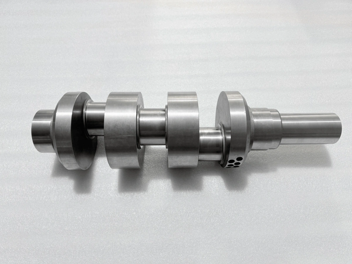
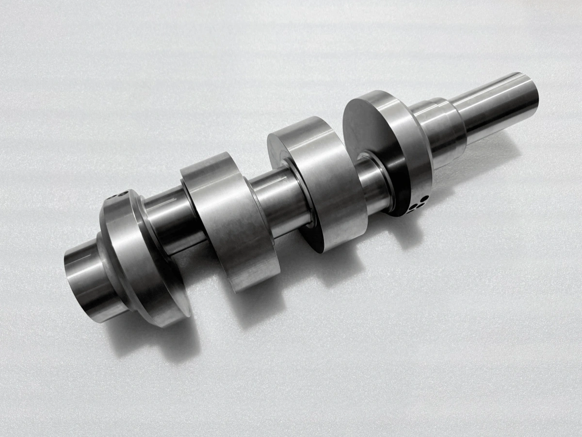
A custom crankshaft manufacturing process must control the relationship between the main journals, offset crankpins and finished bearing surfaces through several machining and treatment stages. For a nitrided alloy-steel design, a typical route starts with material verification, progresses through rough and semi-finish machining, and includes controlled nitriding, any specified final grinding, and separate acceptance checks. The route changes with the drawing, blank condition and service requirements. From a Neway engineering perspective, the useful question at quotation is which features must remain correct after the last operation, and how each will be verified.
Start with the Drawing and the Acceptance Plan
A crankshaft drawing should establish the main datum axis, axial reference and angular orientation before a machining sequence is approved. Journal diameters alone do not define the part. Crankpin offset, phase, journal form, bearing widths, fillets and the relationships between these features may all affect function. The manufacturing review needs to distinguish features that can be checked independently from those that must be related to a common reference.
Read material, heat-treatment, surface-finish and inspection notes together. A requirement that applies after nitriding cannot be accepted from a measurement taken before treatment. Likewise, a specified surface condition may restrict later grinding or polishing. Mark the inspection stage for each critical characteristic and identify any customer approval needed before work continues. This establishes an acceptance plan before machining makes a correction expensive.
Select the Material and Blank as a Complete Specification
Material selection includes the grade, governing specification, product form, heat-treatment condition and required documentation. A grade name on a quotation is not enough to approve a billet. The material certificate should match the agreed purchase requirements and remain traceable to the blank through cutting and subsequent processing. Where additional mechanical testing or stock inspection is required, define it before purchasing.
AISI or SAE 4140 and 42CrMo may appear in discussions of alloy-steel shaft manufacture, but a similar designation or chemistry range does not establish interchangeability. Compare the actual specifications and delivery conditions, then obtain written approval for a proposed substitution. Machining from bar can suit a custom geometry, while a forging may offer a different material-utilization and grain-flow route. Neither is automatically correct: the design, production volume, stock availability and qualification requirements determine the choice.
Compare quotations on that same basis. A lower stock price may exclude a required delivery condition, test or certificate. A near-net blank may reduce metal removal but introduce tooling and qualification work. The RFQ should identify which blank routes are acceptable so those differences remain visible to the buyer.
Plan the Main Axis and Offset Machining Setups Together
Main journals share the intended rotational reference; crankpins occupy controlled offsets from it. A setup that machines an individual cylindrical surface accurately can still place that surface incorrectly relative to the rest of the shaft. Plan how the main axis, axial location and crankpin phase will transfer between operations, including any later grinding setup.
The workholding review should address access, rigidity, clamping force and support locations. Interrupted cuts and changing engagement around webs can load the workpiece unevenly. Supports need to restrain vibration without forcing a flexible shaft into a shape it will not retain when released. Depending on the geometry and equipment, crankpin generation may involve offset turning or milling. CNC turning is part of the available process family, not proof that every feature can be finished in one concentric setup.
Remove Stock in Stages and Recheck the Geometry
Rough machining exposes the effects of the blank's condition, changing section stiffness and released residual stress. Plan stock removal so the remaining shape can be supported and measured throughout the route. Heavy removal from one region should trigger a review of distortion risk before adjacent features approach final size. Any stress-relief operation must be compatible with the material condition and the later treatment specification.
Semi-finishing establishes controlled dimensions for the next operation while retaining deliberate finishing stock where needed. Record whether an allowance is radial or diametral; confusing the two can consume the available correction range. Intermediate checks should confirm that offsets, axial positions and datum features remain recoverable. A final inspection report cannot restore stock that an earlier operation removed. The amount retained must follow the actual treatment and finishing plan, not a universal crankshaft allowance.
Carry the approved sequence into the manufacturing record with clear operation references and inspection points. If the part is unclamped for measurement, distinguish its free condition from its supported machining condition. An unexpected movement should be investigated before the next cut, while material remains available for the approved response.
Complete Secondary Features without Losing the Reference
Oil passages, keyways, threaded holes and other milled features belong in the route only when the drawing requires them. Their position may depend on crankpin phase or a defined angular datum rather than the nearest convenient machined face. Plan tool access and inspection access together, particularly where a feature will become difficult to reach after another operation.
Hole intersections and edges need an agreed deburring and cleanliness method. An accessible external edge does not demonstrate that an internal intersection is free of burrs. Protect fillets and bearing surfaces during handling and secondary machining. Review how these operations interact with nitriding masks, grinding wheel clearance and any later balance correction. The process sequence should resolve those interactions before a finished journal is exposed to avoidable damage.
Define the Nitriding Requirements before Treatment
Nitriding changes the surface region of a suitable steel through nitrogen diffusion. It is generally a low-distortion treatment, but that description does not mean dimensional change is zero. Its response depends on the steel and prior condition, as well as the specified process. It cannot be used to compensate for an unapproved material or an unsuitable core condition.
The treatment instruction should identify the surfaces to be treated, any masked areas, the required hardness and layer-depth criteria, and the condition in which acceptance applies. Specify requirements for the compound layer separately where relevant. Agree how the treatment supplier will demonstrate compliance and how final machining affects the remaining layer. Before release to treatment, check cleanliness, dimensions, allowance and traceability. These are practical handover requirements between machining and heat treatment.
Control Journal Finishing after Nitriding
Some designs require final journal grinding after nitriding; others specify an as-treated condition or a different finishing sequence. Follow the drawing and approved process rather than assuming every nitrided crankshaft must be ground. Where grinding is required, re-establish the intended reference and check the post-treatment condition before deciding how much material can safely be removed.
The CNC grinding plan must satisfy journal size, geometry and surface requirements while retaining the specified treated layer. Grinding heat, wheel condition, coolant delivery and local contact all matter to surface integrity. Polishing is not a substitute for correcting a positional or form error. Do not judge a bearing surface by its shine: dimensional, surface-texture and material-condition requirements need their own evidence on the final specified condition.
Manage the Interfaces that Create Rework
The difficult decisions often occur where two processes meet. A datum convenient for roughing may be unsuitable for final inspection. A journal allowance may accommodate expected distortion but exceed the permitted material removal after treatment. A balance correction may be physically accessible yet conflict with a drawing restriction. Each decision needs to be resolved against the complete route.
For supplier evaluation, ask who owns these interfaces and which operation has authority to stop the part. The machining shop, treatment supplier and inspection provider should work from the same revision and agreed acceptance condition. When a deviation occurs, document it and obtain the required disposition before continuing. Corrective work should include a review of which earlier results are invalidated and which inspections must be repeated.
Keep the Final Inspection Results Separate
Dimensional inspection establishes specified sizes and geometric relationships. Surface-texture measurement addresses the bearing finish. Hardness and layer-depth verification address different aspects of the treated surface. None of these tests, by itself, establishes that every requirement has been met. Select measurement methods, coverage and uncertainty appropriate to the characteristic, and record the datum scheme used for relational measurements.
Nondestructive testing should match the material, anticipated discontinuity location and required coverage. Dynamic balancing addresses mass distribution about the defined rotational reference when the design requires it. A successful balance result cannot compensate for an incorrect crankpin location, and a dimensional report cannot establish freedom from every internal discontinuity. The five linked FAQs below examine these narrower questions; this manufacturing route brings the separate checks into one release plan.
Release the Part against a Traceable Document Package
The release package should connect the material record, applicable process records and required inspection results to the same part and drawing revision. It should state the inspection stage and distinguish measured results from requirements copied into a template. Review missing approvals, incomplete coverage and unresolved deviations before treating a document set as complete.
When an outside process is used, its report should identify the work performed and the applicable acceptance requirements. Keep a clear link to the manufacturing record when the supplier uses its own job reference. A certificate for an unrelated batch or a generic capability statement does not establish the condition of the supplied crankshaft.
Use the agreed conformity decision rule when interpreting results near a limit. Confirm that any rework has been followed by the necessary reinspection. Packaging should protect functional surfaces and maintain traceability without transferring contamination to cleaned features. A shipping instruction establishes a logistics action; it does not replace technical acceptance. The release decision must remain tied to the approved requirements and the evidence that addresses them.
Prepare a Crankshaft RFQ that Defines the Scope
For a manufacturing review, provide the controlled drawing and model, material specification and delivery condition, required quantity, treatment requirements, critical characteristics and inspection deliverables. Identify whether acceptance applies before or after each finishing operation. If NDT or balancing is required, include the applicable specification and reporting expectations rather than asking for an unspecified test.
Send Neway these inputs for a custom CNC machining review. They allow the proposed custom crankshaft manufacturing process, outside-process responsibilities and verification scope to be discussed before the quotation is finalized. Agreeing those details early gives both engineering and purchasing a concrete basis for comparing offers and resolving open requirements.
FAQ