When Does a CNC-Machined Crankshaft Need Dynamic Balancing to ISO 21940?
When Does a CNC-Machined Crankshaft Need Dynamic Balancing to ISO 21940?
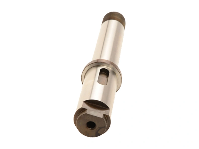
A CNC-machined crankshaft needs dynamic balancing when its drawing or engine balance model requires verified residual unbalance in a defined rotating configuration. For crankshaft dynamic balancing, ISO 21940 provides procedures and tolerances, not a universal requirement triggered by CNC machining. A dimensional inspection pass does not establish mass balance. At Neway, the useful starting question is what configuration and residual-unbalance limit the designer wants accepted.
Start with the rotor requirement
Static balance concerns the resultant unbalance; dynamic assessment also addresses the moment or couple component. A crankshaft can satisfy a static check yet retain an unacceptable couple. Two-plane balancing may therefore be required, but neither the number of planes nor a balance grade should be selected simply because the component is called a crankshaft.
Specify the applicable ISO 21940 part and amendment, the final manufacturing state, and the authority defining acceptance. The decision belongs with the rotor or engine design requirement. Precision machining controls the manufactured geometry; a separate balancing requirement controls the permitted mass-distribution error in the tested configuration.
Choose the rigid or flexible procedure
ISO 21940-11 addresses rotors with rigid behaviour. That classification depends on whether unbalance-induced flexure is negligible relative to the required tolerance over the relevant speed range and support conditions, not merely on the shaft being steel. ISO 21940-12 addresses flexible behaviour, for which a simple low-speed, two-plane result may not establish acceptable balance throughout service.
Have the responsible designer resolve that classification before selecting the test. A flexible rotor may need multiple-speed or service-speed procedures. The balancing-machine test speed is not the maximum service speed: a rigid rotor can often be measured below operating speed if the measurement remains valid. Do not substitute a convenient test speed for the specified service speed when setting the tolerance.
Turn a grade into measurable limits
A G grade alone is incomplete acceptance information. For rigid behaviour, the chosen grade and maximum service speed establish permissible residual specific unbalance; rotor mass is then needed to obtain total permissible residual unbalance. The governing method allocates that allowance to the tolerance planes. Record the resulting limits and units, rather than reporting only that the shaft meets a grade.
Check the measuring system's verification status and account for relevant balancing errors. Repeat mounting or an agreed verification check can expose setup-dependent results. The acceptance method must define how such errors are treated; a very small displayed value is not proof that the actual residual unbalance is equally small.
Fix the assembly and correction conditions
State whether the test includes specified plugs, keys, timing components, a damper, flywheel, or other fitments. Record the required key convention. Where a V-type engine design requires bobweights, use its approved rotating and reciprocating mass model and calculated values. Do not apply a generic percentage or transfer bobweights from another engine. The balanced bare shaft and the intended assembly are not automatically equivalent.
Define correction planes, angular reference, permissible zones, and correction radii. Removing a given mass at different radii produces different corrections, because unbalance is mass multiplied by radius. A machine's suggested correction does not authorize drilling a restricted counterweight or altering a fatigue-sensitive feature. Complete the agreed CNC turning and other stock-removal operations before final balance verification when they can affect mass distribution. All corrections must preserve the drawing's geometry and structural requirements.
Know what a balance pass excludes
Balancing addresses residual rotating unbalance in the specified test condition. It does not verify journal diameter, alignment, surface integrity, or material properties. Nor does it by itself eliminate reciprocating inertia forces, combustion excitation, torsional vibration, or structural resonance. A correctly balanced rotor can still vibrate in an unsuitable support system; an engine vibration complaint needs its own diagnosis.
Define the release record before manufacture
Request rotor identity, drawing revision, applicable standard, behaviour classification, mass, maximum service speed, test speed, assembly state, and any bobweight reference. Include plane locations, grade or explicit limits, final residual-unbalance values, correction details, machine verification, error treatment, and disposition. Retain magnitude and angular position for each reported residual-unbalance vector, referenced to the stated planes and phase datum. That allows a later check to compare the same physical condition rather than two incompatible machine summaries. Keep this report within the agreed precision-part release evidence. For a Neway RFQ, provide the balance specification and assembly definition with the drawing so scope and acceptance can be resolved before quoting.