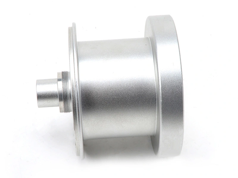
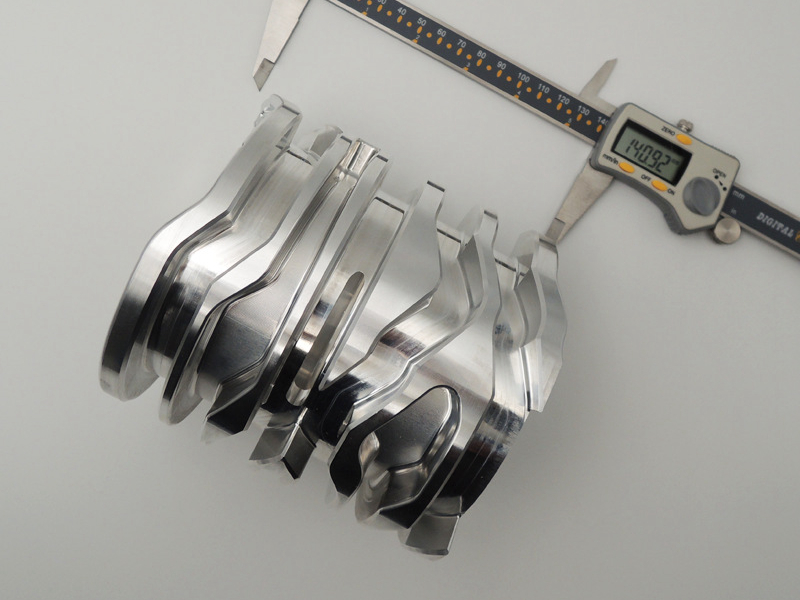
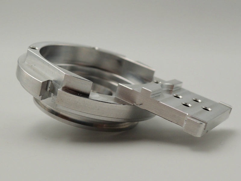
CNC Machined Parts for Oil & Gas: Materials, Durability, and Critical Applications
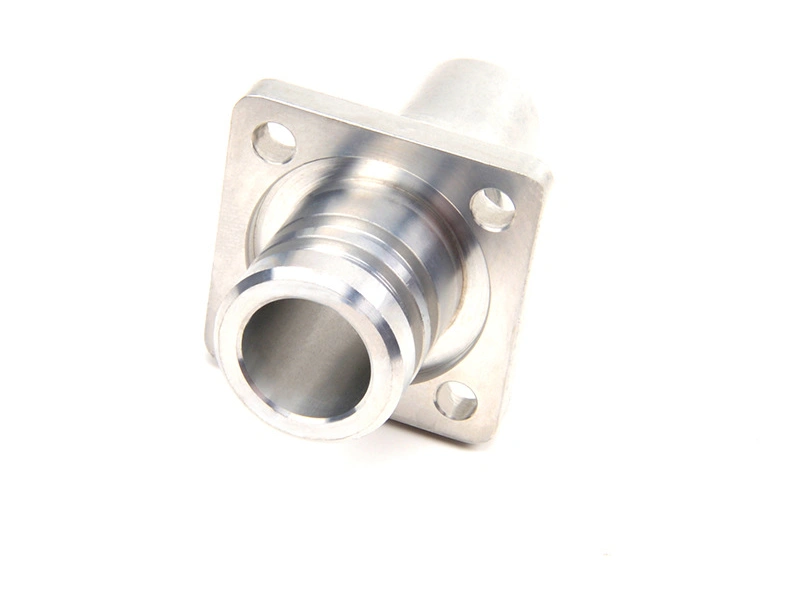
CNC machined parts for the oil and gas industry are reliable only when part function, service exposure, exact material condition, manufacturing route, critical geometry, and acceptance evidence are specified as one system. Pressure-boundary components, sealing interfaces, threaded connections, wear parts, and structural housings do not share one universal alloy or tolerance plan. The correct CNC machined parts strategy depends on the fluid, pressure and temperature basis, H2S or chloride exposure, loads, mating components, maintenance cycle, and governing product specification. Buyers should provide those inputs with the drawing and required record package before requesting material, process, cost, or delivery commitments.
CNC machining can control bores, threads, seal lands, datums, ports, and wear clearances, but machining alone does not create service qualification. Durability can be lost through localized corrosion, wall loss, hydrogen-related cracking, galling, erosion, coating buildup, residual-stress movement, burrs, or an inspection method that cannot reach the critical feature. A sound sourcing plan connects each credible failure to a prevention step and a final-state verification. That connection gives procurement a defensible basis for comparing suppliers instead of relying on alloy labels, machine lists, or a nominal piece price.
Why Oil & Gas Machined Parts Demand High Durability
Oil and gas machined parts demand high durability because a small loss of section, seal contact, thread engagement, alignment, or wear clearance can change containment and equipment availability. The relevant exposure may combine internal pressure, corrosive production fluids, seawater, abrasive solids, vibration, thermal cycles, and repeated assembly. Remote location increases the consequence of failure, but it does not define the technical requirement. The drawing and purchase specification must translate the actual service case into material condition, critical characteristics, surface requirements, examination, testing, traceability, and acceptance records.
Durability is therefore a chain rather than a single material property. Strength resists load only while the remaining section and material condition support it. Corrosion resistance depends on alloy, heat treatment, hardness, microstructure, surface condition, fluid chemistry, temperature, stress, and time. Wear behavior depends on contact pressure, motion, lubrication, debris, clearance, and mating materials. Manufacturing can protect or weaken that chain through stock control, setup sequence, tool condition, heat generation, deburring, special processing, cleaning, and final inspection. Buyers should rank these mechanisms by the component's function and failure consequence.
Common CNC Machined Parts Used in Oil & Gas Equipment
Valves and Flow-Control Parts
Valve bodies, seats, stems, cages, retainers, adapters, and flow-control inserts combine pressure, motion, and sealing functions. Their critical features may include a seat angle, seal diameter, stem guide, pressure-wall transition, port position, or thread-to-shoulder relationship. The machining route should keep functional datums consistent through roughing and finishing, then control burrs and edge damage where flow paths intersect. Validation must match the feature: dimensional inspection can verify geometry, while the specified non-destructive examination or assembly test addresses different evidence. A pressure test does not replace material, thread, or surface verification.
Connectors and Threaded Fittings
Connectors, couplings, nipples, threaded fittings, and instrument interfaces need more than a nominal thread callout. The contract should identify the thread standard or approved proprietary drawing, class or designation, gauge practice, gauge plane, shoulder relationship, sealing mechanism, surface condition, and permitted repair. Form error, lead error, burrs, contamination, axis mismatch, or coating in the thread can cause galling, incomplete engagement, unstable preload, or leakage. Thread gauges confirm only the characteristics covered by their design, so additional geometry or functional evidence may be required by the connection specification.
Sealing Components
Seal carriers, gland parts, seats, grooves, retaining rings, and mating faces must be specified for the actual seal mechanism. An O-ring bore, gasketed face, metal seat, dynamic stem seal, and threaded shoulder require different combinations of size, form, surface texture, lay, edge condition, cleanliness, and coating state. One roughness value cannot describe waviness, scratches, chatter, contact width, or a continuous leak path. Buyers should state the seal data, mating material, pressure direction, assembly condition, prohibited defects, final finish state, inspection method, and any required functional test.
Bushings and Wear Parts
Bushings, sleeves, guides, and sacrificial wear elements require a clearance and material-pair decision, not an isolated bore tolerance. Operating temperature, lubrication, contamination, contact load, speed, shaft finish, housing fit, and coating or heat treatment can all change the final clearance. Too little clearance can cause seizure after thermal expansion or coating; too much can increase impact, leakage, vibration, and uneven wear. The inspection plan should verify the released ID, OD, roundness, length, edge condition, and mating assumptions in the specified final condition.
Housings and Structural Components
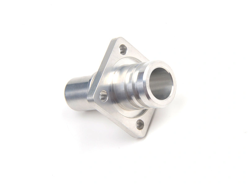
Housings, covers, manifolds, and mounting structures often combine ports, threaded features, sealing planes, bearing bores, and mounting datums in one part. The main risk is the relationship among those features after all material removal and finishing, not the accuracy of each setup in isolation. Thin walls can move after unclamping, and rough machining can redistribute residual stress before finish operations. A useful plan identifies the functional datum scheme, rough-to-finish sequence, any stabilization step, inaccessible intersections, coating allowance, and final measurement setup before tolerance commitments are accepted.
Component Type | Functional Decision | Primary Failure to Control | Evidence to Request |
|---|---|---|---|
Valve parts | Identify pressure boundary, flow path, motion guide, and seal interfaces | Leak path, sticking, erosion, wall reduction, or unstable shutoff | Material record, critical-feature report, required NDE, and specified assembly test |
Connectors | Define thread, shoulder, seal mechanism, engagement, and mating component | Galling, cross-threading, poor preload, misalignment, or leakage | Applicable gauge results, shoulder or axis inspection, surface check, and traceability |
Sealing components | Match form, texture, lay, edge, cleanliness, and finish state to the seal | Seal cutting, uneven contact, debris retention, or continuous leakage path | Final-state geometry, surface measurement, visual criteria, and required leak evidence |
Bushings | Set operating clearance from material pair, load, motion, temperature, and lubrication | Seizure, accelerated wear, vibration, impact, or loss of guidance | ID, OD, roundness, finish, mating data, and final treatment condition |
Housings | Protect datum relationships among bores, ports, sealing planes, and mounts | Distortion, assembly stress, port mismatch, thin wall, or eccentric loading | Datum-based final inspection, wall or feature checks, treatment records, and release status |
How to Select Materials for Oil & Gas CNC Machined Parts
Materials for oil and gas CNC machined parts should be selected from the service environment, mechanical duty, failure mechanism, product specification, and required final condition. An alloy family is not a complete specification: grade, product form, heat treatment, hardness, microstructure where controlled, and applicable sour-service limits can change performance and machinability. The RFQ should state fluid composition, H2S and chloride conditions where relevant, pressure and temperature basis, loads, wear or galling risk, coating system, mating materials, traceability, and governing standards. A corrosion or materials specialist should resolve conditions beyond the drawing's established design basis.
Stainless Steel
Stainless steel CNC machining can serve wet, chemically exposed, and pressure-related components when the exact grade and condition fit the environment. Austenitic, martensitic, precipitation-hardening, and duplex stainless steels differ in strength, hardness, chloride resistance, H2S limits, heat-treatment response, magnetic behavior, and machining risk. Stainless is not automatically immune to pitting, crevice corrosion, stress-corrosion cracking, or galling. Buyers should control grade and heat identity, required condition, hardness or heat treatment, contamination limits, passivation or other finishing, and final dimensions after processing.
Superalloy
Superalloy CNC machining is appropriate when a specified nickel- or cobalt-base grade provides needed corrosion, temperature, or mechanical performance that simpler alloys cannot meet. The benefit is grade- and environment-specific, not a universal safety margin. Work hardening, low thermal conductivity, tool wear, burr formation, and residual stress can change feature size and surface integrity during machining. The supplier should show stock identity, condition, rough-to-finish strategy, tool-life control, heat input management, deburring, and a final inspection plan suited to the component's seal, thread, and datum risks.
Carbon Steel
Carbon steel CNC machining offers strength, availability, and economical cutting for bodies, supports, shafts, and connectors when corrosion is managed by the complete design. The decision must include grade, product form, heat treatment, weld or forging history where applicable, hardness limits, coating, corrosion allowance, and service chemistry. Coating does not correct mixed material, cracks, decarburization, poor threads, or out-of-tolerance geometry. Because plating or coating can change thread fit, bore size, edge condition, and seal contact, the drawing must state which dimensions apply in the final coated condition.
Bronze
Bronze can suit bushings, guides, thrust elements, and sacrificial wear interfaces when the specified alloy supports the load, motion, lubricant, temperature, fluid exposure, and mating material. Bronze families differ in strength, corrosion behavior, lead content, galling resistance, and machinability, so the family name alone is not an approval basis. Buyers should check galvanic compatibility, shaft or housing hardness and finish, press-fit allowance, operating clearance, edge geometry, and whether the wear part must be replaceable without damaging the higher-value component.
Material Family | Fits When | Key Limitation | RFQ Confirmation |
|---|---|---|---|
Stainless steel | The specified grade and condition meet corrosion, strength, temperature, and code requirements | Family name does not resolve chloride, H2S, galling, hardness, or heat-treatment limits | Grade, product form, condition, heat identity, environment, finishing, and final acceptance |
Superalloy | A defined severe environment requires its grade-specific corrosion or temperature capability | High cost and machining difficulty do not guarantee suitability for an unspecified service case | Exact grade, condition, material specification, service basis, critical features, and record package |
Carbon steel | Strength and cost objectives are compatible with an approved corrosion-control system | Coating damage, hardness limits, corrosion allowance, and final dimensional change require control | Grade, heat treatment, hardness, coating specification, masking, allowance, and post-finish inspection |
Bronze | A specified grade supports sliding, guidance, anti-galling, or sacrificial-wear duty | Load, galvanic pair, temperature, chemistry, fit, and lubrication can change suitability | Alloy, mating material, load, motion, lubricant, clearance, finish, and replacement strategy |
Critical Dimensions, Tolerances, and Sealing Surface Control
Critical tolerances for oil and gas machined parts are the limits that protect sealing, containment, thread function, alignment, wall thickness, motion, and assembly. They should be assigned from failure consequence and the functional datum scheme, not copied from a general tolerance block or tightened uniformly. ASME Y14.5 or ISO 1101 can define geometric controls when the drawing states the selected standard and edition consistently. The manufacturing and inspection setups must realize the same datum logic. Machine positioning accuracy or CMM resolution cannot be used as a finished-part tolerance guarantee.
Sealing surfaces require a complete final-state specification. Size, form, flatness, roundness, runout, surface texture, lay, waviness, edge break, scratches, cleanliness, and coating condition may affect the leak path. A universal Ra range is not defensible across O-rings, gaskets, metal seats, dynamic seals, and threaded shoulders. The designer should specify the functional requirement and measurement method for the defined zone. Inspection should occur after any operation that can change the feature, including heat treatment, lapping, plating, coating, cleaning, or assembly preparation, with measurement uncertainty considered in the acceptance decision.
Critical Feature | Functional Requirement | Control and Validation | Failure if Misapplied |
|---|---|---|---|
Threaded connection | Provide specified engagement, load transfer, alignment, and sealing relationship | Approved thread definition, applicable gauges, shoulder or axis checks, burr and surface inspection | Galling, cross-threading, variable preload, incomplete seal contact, or leakage |
Sealing face | Create continuous contact without damaging the selected seal or trapping contamination | Final-state form, texture, lay, edge and visual criteria, plus specified functional test | Uneven compression, seal cutting, debris retention, unstable friction, or leak path |
Precision bore | Locate and guide the mating feature while maintaining fit and wall condition | Diameter, form, position or axis relation using an accessible method and functional datums | Interference, looseness, eccentric loading, wall reduction, wear, or poor seal alignment |
Bushing clearance | Maintain controlled motion across temperature, load, lubrication, and final treatment | Final ID and OD, roundness, finish, mating size, fit calculation, and operating assumptions | Seizure, impact, vibration, accelerated wear, or loss of positional guidance |
Mounting datum set | Reproduce assembly location and orientation across bores, ports, faces, and fasteners | Datum-based position, orientation and form inspection after release-affecting operations | Forced assembly, residual load, misalignment, port mismatch, or distorted seal contact |
Why Pressure Integrity and Corrosion Resistance Cannot Be Treated Separately
Pressure integrity and corrosion resistance cannot be treated separately because material degradation changes the geometry and stress state that contain pressure. General corrosion can reduce wall thickness, while pitting can create a localized stress raiser or leak path. Crevice attack can develop at a seal interface, and environment-sensitive cracking can grow with limited visible material loss. At the same time, form error, tool damage, sharp transitions, poor surface condition, or residual stress can intensify local exposure. Material selection controls susceptibility; machining and finishing control the manufactured condition; NDE, dimensional inspection, and pressure or leak testing provide different evidence.
Consider a hypothetical corrosion-resistant steel valve adapter with a threaded connection, a metal seal land, and a datum-controlled port. The engineering risk is not merely choosing the wrong alloy. Lost heat identity, excess hardness for a specified sour-service condition, thread burrs, seal-land chatter, port mislocation, or coating buildup can each defeat the intended design. A controlled route would verify material and condition, protect the heat number, rough and finish from functional datums, deburr without rounding the seal edge, apply any specified finishing, and inspect the final state. The buyer would release the lot only after the material, dimensional, surface, NDE, and required assembly-test records meet their separate acceptance criteria. This is an engineering scenario, not a Neway customer case.
How Buyers Should Evaluate a Supplier for Oil & Gas Machined Parts
Buyers should evaluate an oil and gas machining supplier by testing whether its documented route can reproduce the specified material condition, critical features, special processes, inspection evidence, and traceability on the buyer's part. A quality certificate, machine list, or similar industry example is useful for screening but does not prove part-specific capability. Contract review should identify drawing revision, standards, material and heat identity, critical characteristics, manufacturing and inspection datums, hold points, sampling or full inspection, nonconformance authority, change notification, record retention, packaging, and final release requirements.
The supplier workflow should connect material purchase and receiving status to sawing, rough machining, any stabilization or heat treatment, finish machining, deburring, cleaning, coating or other approved outside processing, final inspection, document review, and shipment release. Audit one representative serial number or lot in both directions, then use a first article or controlled trial lot to test the plan. The RFQ should include service inputs, exact material and condition, mating data, pressure and temperature basis, critical features, finish state, NDE or test requirements, trace level, required records, quantity, delivery need, and all approved deviations. Repeat production should be approved only after open technical exceptions and trial evidence are accepted.
Conclusion
CNC machined parts for oil and gas require an integrated decision across function, service environment, exact material condition, machining route, critical geometry, surface state, inspection, and records. Stainless steel, superalloy, carbon steel, and bronze each fit defined combinations of corrosion, strength, temperature, wear, galling, availability, and cost. None is automatically durable by family name. The same boundary applies to machining: a precise operation does not establish pressure rating, corrosion qualification, or field life. Those outcomes remain governed by the approved design, material, manufacturing, assembly, examination, testing, and acceptance basis.
Before sourcing CNC machined parts, classify each component as pressure-boundary, sealing, threaded, wear, alignment, or structural, then connect its leading failure modes to controls and evidence. Use the oil and gas industry page to frame the application, but place the project-specific decision in the RFQ: service conditions, drawing revision, material state, critical features, special processes, final finish, inspection and test requirements, traceability, records, quantity, and delivery. That package lets suppliers quote the same technical scope and lets buyers release only verified results.
FAQ
What Types of CNC Machined Parts Are Commonly Used in Oil and Gas Equipment?
Which Materials Are Best for CNC Machined Parts in Corrosive Oil and Gas Environments?
Why Are Corrosion Resistance and Pressure Integrity Critical for Oil and Gas Machined Parts?
What Tolerances and Surface Requirements Matter Most in Oil and Gas Components?
How Should Buyers Evaluate a Supplier for CNC Machined Parts Used in Oil and Gas?