ما الفرق بين التفاوتات البُعدية والهندسية في تشغيل CNC؟
بصفتنا مهندسين، نستخدم كلًّا من التفاوتات البُعدية والهندسية للتحكم في كيفية توافق الجزء المُشغَّل باستخدام الحاسب الآلي (CNC) وعمله وتجميعه في العالم الحقيقي. تعمل هاتان الفئتان معًا، ولكنّهما ليستا متماثلتين.
التفاوتات البُعدية: التحكم في الحجم والخصائص الخطية
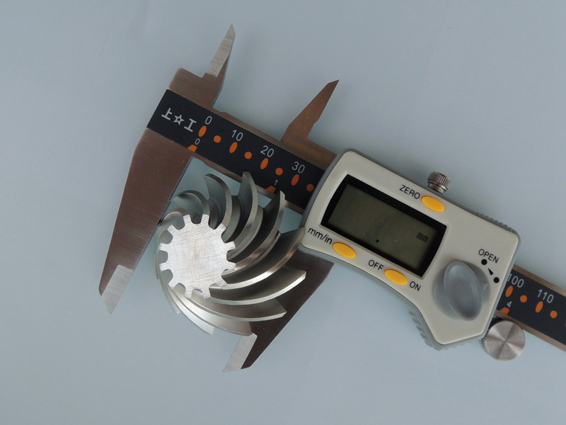
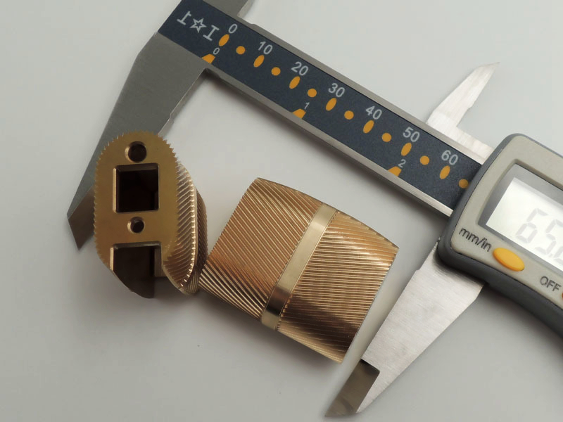
تحدد التفاوتات البُعدية مقدار الاختلاف المسموح به في الحجم، بما في ذلك الطول والعرض والقطر والسماكة وحجم الفتحة والأبعاد الأخرى. على سبيل المثال، عمود بقطر 10.00 مم مع تفاوت ±0.02 مم يعني أن الحجم الفعلي يمكن أن يتراوح بين 9.98 مم و10.02 مم. هذه الحدود تكون عادة كافية للخصائص غير الحرجة أو التركيبات القياسية وترتبط مباشرة بقدرات الماكينة واستقرار العملية، كما نضمن في خدمات التشغيل باستخدام CNC والطحن والخراطة. عندما تكون التفاوتات ضيقة عبر ميزات متعددة في نفس المكون، نطبّق إعدادات تفصيلية واستراتيجيات فحص كجزء من خدمات التشغيل الدقيقة ومعالجة الأشكال المعقدة من خلال خدمات التشغيل متعدد المحاور. الإجابة الأساسية التي تقدمها التفاوتات البُعدية هي: «هل هذا العنصر بالحجم الصحيح ضمن النطاق المحدد؟»
التفاوتات الهندسية: التحكم في الشكل والاتجاه والموقع
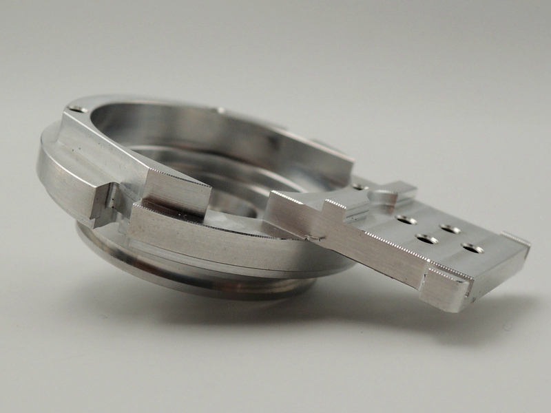
تتجاوز التفاوتات الهندسية (GD&T) مفهوم الحجم. فهي تتحكم في كيفية ارتباط الخصائص ببعضها في الفضاء ثلاثي الأبعاد: الاستقامة، التسطيح، التدوير، الأسطوانية، التعامد، التوازي، الموضع، التدوير الكامل وغير ذلك. قد يحقق الثقب تفاوتاته البُعدية ومع ذلك يكون في موضع غير محاذٍ؛ تمنع التفاوتات الهندسية ذلك. بالنسبة للتجميعات الوظيفية — مثل أغلفة التوربينات في السبائك عالية الحرارة أو التجاويف الدقيقة في مكونات الأجهزة الطبية والسيارات — تضمن الضوابط الهندسية المحاذاة والإغلاق وعمر التحمل وتوزيع الحمل المتسق. فهي تُعرّف "مدى جودة الشكل الهندسي" بدلاً من مجرد "مدى كِبر الحجم".
كيف تعمل معًا في المشاريع الواقعية
في التطبيق العملي، ندمج كلًّا منهما معًا:
بالنسبة للأجزاء الهيكلية المصنوعة من سبائك الألومنيوم 6061-T6، تضمن التفاوتات البُعدية الحجم الصحيح للهيكل الخارجي، بينما تضمن التفاوتات الهندسية استواء الأسطح ومواقع الفتحات الدقيقة.
في المكونات المصنوعة من الفولاذ المقاوم للصدأ SUS304 مثل المنافذ، تحافظ تفاوتات الموضع والتعامد على محاذاة قنوات السوائل.
في المكونات الحرجة في إنكونيل 718 أو تيتانيوم Ti-6Al-4V ضمن تطبيقات الفضاء الجوي، تحمي التفاوتات الهندسية أسطح التحمل وخطوط الإغلاق في ظروف حرارية وميكانيكية شديدة.
تتطلب البوليمرات الهندسية مثل PEEK ضبطًا مناسبًا لـ GD&T لإدارة الزحف والإجهاد أثناء التجميع والتوافق مع المكونات المعدنية.
يتأثر الأداء النهائي أيضًا بالتشطيبات السطحية. قد يكون تشطيب "كما هو مشغَّل" كافيًا للمناطق غير الحرجة، بينما تستفيد الأسطح الخاصة بالإغلاق أو الانزلاق من خشونة مُتحكم بها عبر خدمات تلميع أجزاء CNC لدعم الدقة الهندسية وطول العمر الوظيفي. تعتمد صناعات مثل الطيران والفضاء والأجهزة الطبية والسيارات اعتمادًا كبيرًا على تطبيق GD&T بدقة، لأن أي خطأ في الاتجاه أو الموضع قد يؤدي إلى فشل ميكانيكي أو تسرب أو ضوضاء أو عدم مطابقة للمعايير — حتى عندما تكون جميع الأبعاد "ضمن التفاوت". إن تحقيق التوازن الصحيح بين التفاوتات البُعدية والهندسية يساعد في تحسين قابلية التصنيع وتكاليف الفحص والموثوقية: دقيق حيث يلزم، واقتصادي حيث لا يلزم.


