Will HIP treatment cause part deformation?
Yes. HIP treatment can cause measurable dimensional change, but it should not cause unacceptable deformation when geometry, material condition, residual stress, local porosity, support, and post-HIP stock are planned before the cycle. Hot Isostatic Pressing is intended to close sealed internal porosity and improve material integrity, not reshape the component. Uniform densification may reduce overall size, whereas bow, twist, sag, or datum shift indicates nonuniform response. Thin or unsupported features, uneven section thickness, prior manufacturing stress, and excessive creep exposure raise the risk. Buyers should send the drawing, alloy grade, product form, heat-treatment condition, porosity evidence, critical tolerances, datum scheme, previous process route, and final precision machining requirements with the RFQ.
The HIP Process and Its Intent
HIP places a component in a pressure vessel and applies inert-gas pressure and high temperature at the same time. Metal HIP cycles commonly use pressures on the order of 100-200 MPa, while temperature, dwell, heating, cooling, and pressure release must follow the alloy, product form, material specification, and property target. Heat enables diffusion and creep; external pressure collapses sealed internal microporosity and voids in castings, powder products, and DMLS 3D printed parts. Open pores connected to the surface are exposed to vessel gas and may not close. For safety-critical parts in aerospace and aviation or power generation, property improvement is credible only when internal-defect closure, material condition, and final geometry are all verified.
When and Why Deformation Can Occur
HIP can change dimensions through two different mechanisms: pore collapse produces densification shrinkage, while stress relaxation, high-temperature creep, gravity, fixtures, and uneven geometry can change shape. Isostatic pressure reduces directional loading but does not make the thermal and structural response uniform. A risk review should therefore examine initial density distribution, thin walls, long arms, sharp thickness transitions, partially machined blanks, build orientation, support conditions, and residual stress from additive manufacturing, casting, welding, or heavy machining.
Residual Stresses from Prior Manufacturing: Parts with residual stress from CNC machining, casting, welding, or SLM 3D printing can move as HIP temperature lowers yield strength and relaxes locked-in stress. A controlled stress relief heat treatment before HIP may reduce risk when the alloy specification and process sequence allow it. The route sheet should identify roughing, welding, build orientation, support removal, straightening, and prior heat exposure so movement is not attributed to HIP pressure alone.
Non-Uniform Section Thickness: Thick-to-thin transitions can move because temperature, stiffness, creep resistance, and local pore-collapse strain are not uniform. Thin walls beside heavy bosses, ribs, or flanges are more likely to bow or lose flatness. Spatially uneven porosity can also create differential shrinkage even when external pressure is uniform. Drawing review should flag walls, unsupported spans, datum faces, and features with too little stock for correction after HIP.
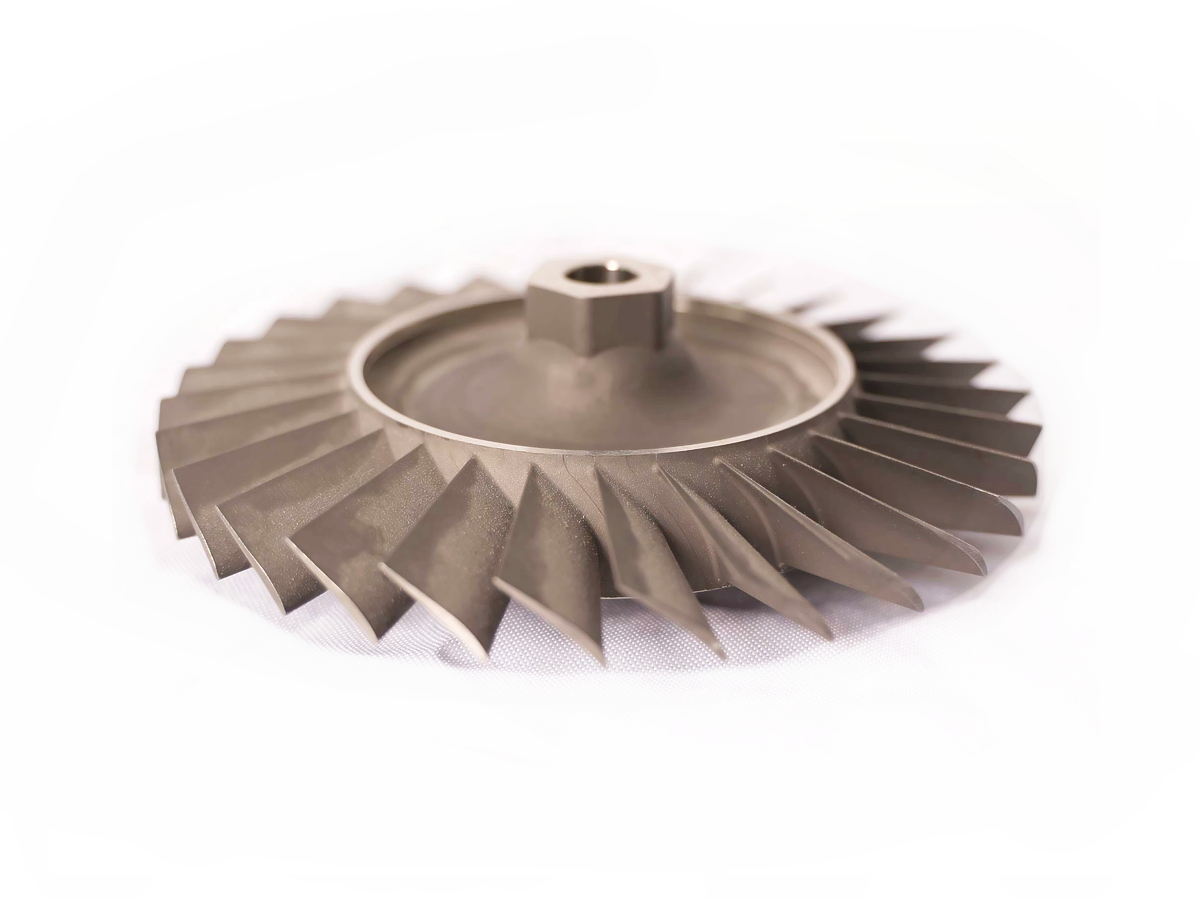
Support-Limited Geometries: Long arms, overhangs, fins, tall posts, and cantilevered features can sag at HIP temperature under their own weight. Orientation, loading method, contact points, fixture stiffness, thermal expansion, and fixture-part compatibility can change the result. Support must not contaminate, react with, indent, or constrain a functional surface. If qualified support is impractical, the part may need temporary stock, a revised sequence, or a prototype cycle.
Surface-Connected Porosity: Pores open to the surface may remain because pressure reaches both sides of the pore wall. This usually leaves a defect rather than causing gross distortion, but it can expose edge pits or near-surface voids after post-HIP CNC milling or grinding. The RFQ should identify whether surface-connected indications affect sealing, fatigue, corrosion, coating, or only appearance, and should define the inspection and disposition route.
Minimizing the Risk of Deformation
Deformation risk is controlled by establishing the expected densification strain, choosing an alloy-specific cycle, supporting vulnerable geometry, retaining correction stock, and measuring the same datums before and after HIP. A supplier should not promise zero movement before reviewing the drawing and process history. The practical goal is movement that is predicted, measured, and kept inside the approved machining allowance and final geometric-tolerance plan.
Design for HIP: Use gradual section transitions where function permits, retain realistic post-HIP stock, identify support or contact surfaces, and define stable datums. For additive manufacturing, this is closely related to DFAM (Design for Additive Manufacturing), because build orientation, support removal, powder evacuation, local density, and stress-relief sequence affect HIP response. Near-net-shape geometry should include shrinkage compensation only after representative evidence establishes its direction and magnitude.
Process Optimization: The HIP cycle must match alloy chemistry, product form, starting density, geometry, and the required downstream material condition. Inconel 718 and Ti-6Al-4V require different thermal windows, dwell, cooling, and heat-treatment integration. Excess temperature or time can increase creep or alter microstructure, while inadequate exposure can leave unacceptable internal porosity. The governing material or customer specification takes priority over a generic recipe.
Pre- and Post-Processing: Record pre-HIP geometry before loading, then repeat inspection after the part returns to the specified measurement temperature. Use the same datum definition, fixture logic, calibrated method, and reporting convention so size change, form error, and local surface change are not mixed. Final machining can restore datums, holes, seal faces, and the required surface finish, but it cannot recover a thin wall or feature that moved outside available stock.
Engineering Verdict
HIP treatment is unlikely to push a well-designed, adequately supported, dimensionally planned part outside its approved correction allowance, but it can deform thin, stressed, nonuniform, or poorly supported geometry. Material name and final tolerance alone are not enough to judge risk. The release plan should define alloy condition, starting density or porosity map, HIP specification, rough stock, datum scheme, thin-wall limits, support method, pre- and post-HIP measurements, acceptable shrinkage, geometric limits, and final machining. A representative first article or prototype HIP trial should precede production when geometry is slender, starting density varies, no correction stock remains, or prior stress history is uncertain.