How should machining vibration be handled when it occurs?
Machining vibration should be handled by stopping the unstable cut, identifying whether the cause is forced vibration or self-excited chatter, then changing rigidity, speed, engagement, tooling, or support before more parts are produced. A quick parameter change can save a part, but a lasting fix needs evidence from the sound, witness marks, spindle load, tool wear, setup stiffness, and inspection data. If chatter marks appear on sealing faces, thin walls, bores, or datum features, the affected parts should be isolated until surface finish, size, and possible edge damage are checked against the drawing.
Immediate Investigation and Source Identification
The first diagnostic step is to separate the vibration source instead of treating every noise as the same problem. Forced vibration comes from a repeatable external input, such as an unbalanced holder, a damaged insert, spindle bearing wear, interrupted stock, loose clamps, or chip recutting. Self-excited chatter comes from the cutting process feeding energy back into the tool-workpiece-machine system. A previous pass leaves a wavy surface, the next tooth cuts variable chip thickness, and the oscillation grows. Forced vibration is usually solved by removing the physical source. Self-excited chatter usually needs a change in speed, chip load, tool overhang, engagement angle, or workpiece support.
Start with checks that can be verified without rewriting the whole process. Check and tighten all clamping and fixturing, including the vise, jaws, pallets, clamps, work stops, tool pull stud, collet, holder, and any soft support under the part. A thin plate, blade-like feature, or long boss may behave like a spring even when the fixture looks solid. A controlled one stop service process should record which setup produced the vibration, which feature was being cut, and whether the problem appeared during roughing, semi-finishing, or final finishing. During prototyping, this record is valuable because it shows whether the part design needs extra machining stock, temporary tabs, or a different datum sequence before production begins.
Corrective Actions: Parameter and Toolpath Adjustments
The fastest controlled correction is often to alter the spindle speed, because chatter depends on the dynamic relationship between tooth passing frequency and the machine-tool-workpiece system. A change of roughly 10-20% up or down can move a cut away from an unstable zone, but the safe direction depends on material, tool diameter, holder, and available torque. Some machines allow spindle speed variation, which can break a repeating harmonic pattern during roughing. That function should be tested on the actual feature, because speed modulation may not protect a tight finishing surface if the tool is already worn or the part is unsupported.
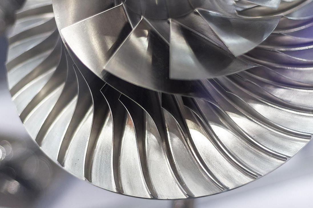
Changing feed rate and depth of cut should be done as a pair, not as random slowing down. A reduced radial depth of cut (step-over) often lowers the engagement angle and cutting force, which helps end mills in pockets or corners. Reducing axial depth can help on long tools, but it may add passes and heat if the chip becomes too light. A slightly increased feed rate can sometimes stabilize a rubbing tool by forming a real chip, yet this only works when the edge, holder, and fixture can carry the load. For a multi-axis machining service, tool orientation, lead angle, and constant-engagement paths can keep the cutter away from high-contact corners that trigger vibration.
Tooling and Toolholder Strategies
Tooling changes should reduce overhang and improve damping before the process gives up material removal rate. Use the shortest possible tool extension that still clears the fixture and workpiece, and choose the largest possible tool diameter that can access the feature without rubbing adjacent walls. The holder matters because runout and grip stiffness decide whether each tooth shares the cut evenly. heat shrink holders may provide low runout and strong grip for many milling tools. hydraulic holders can add useful damping when the tool length is moderate. damped toolholders are a higher-cost option for long-reach boring, deep pockets, and slender features where ordinary holders cannot keep the vibration inside the surface finish requirement.
Cutter geometry can also interrupt the vibration loop. A tool with uneven flute spacing changes the time between cutting-edge impacts, while a variable helix angle changes how the edge enters and exits the material along the flute. These designs do not replace rigidity, but they can make a marginal process stable enough for finish machining. In CNC milling service, they are most useful when the same feature repeatedly shows chatter at a specific wall height, corner radius, or tool stick-out. The buyer should ask whether the proposed tool is chosen for access, material, finish, burr control, or vibration control, because each reason can lead to a different cutter.
Addressing Workpiece and Machine Rigidity
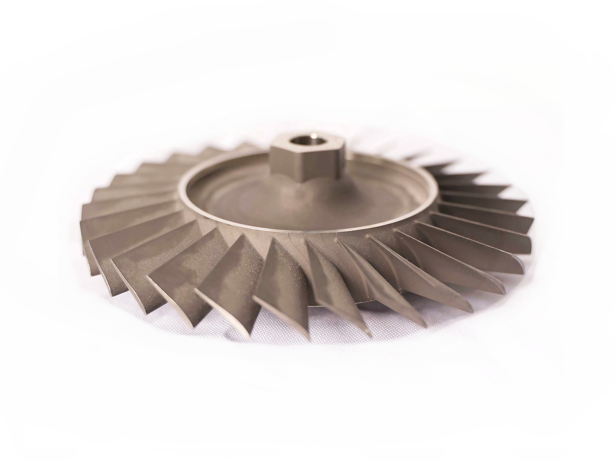
If vibration persists after speed, feed, engagement, and holder changes, the part or machine may be the limiting spring in the system. For long, thin, or ring-shaped features, sacrificial supports can hold material during roughing and be removed after the geometry is stable. Temporary tabs, backfill, soft jaws, rest pads, tailstock support, or an alternate roughing datum may be needed before the final surface is cut. Chip evacuation also matters because recutting chips can mimic chatter and damage the finish, so a high-pressure coolant system may help only when chips, not structural resonance, are the cause.
When the machine structure, spindle condition, or fixture cannot support the cut, the corrective action becomes a sourcing and routing decision. A tight precision machining service feature may need a more rigid machine, a shorter tool path, semi-finish stock control, or a separate finishing setup. Chatter can leave residual stress, surface tearing, and microscopic edge damage, so later heat treatment for CNC machining or a PVD coating should not be used to hide an unstable machining condition. The clean closeout is to document the root cause, the changed parameter or support method, the inspection evidence, and the rule for stopping production if the same vibration returns.