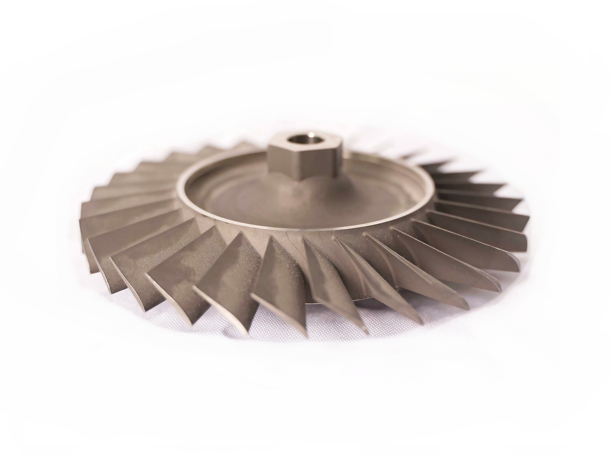
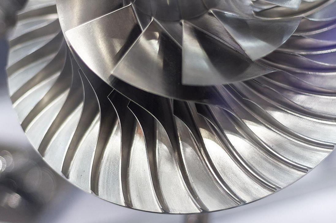
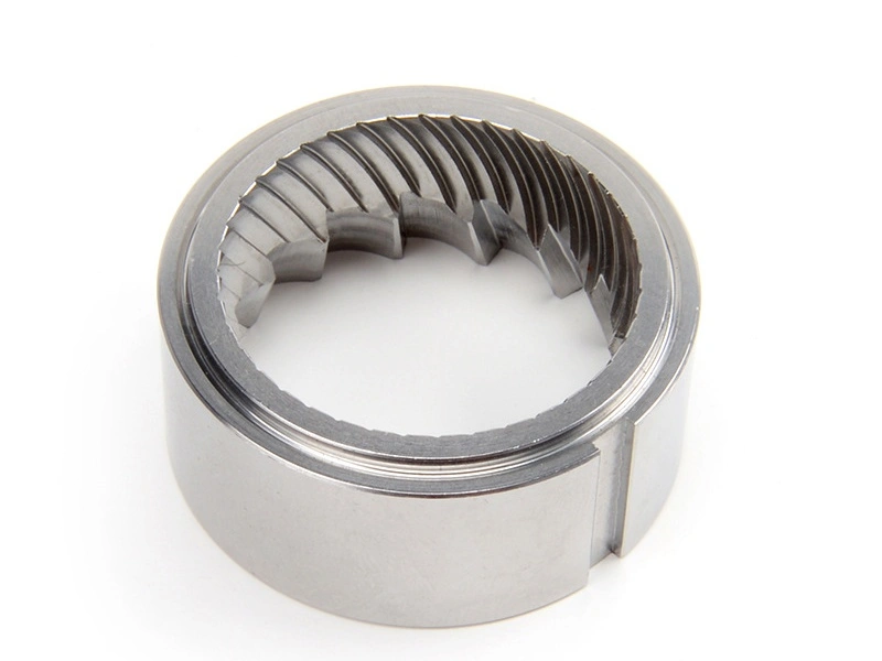
How can deformation of thin-walled superalloy parts be controlled during machining?
Thin-walled superalloy parts are controlled during machining by managing residual stress, heat, cutting force, clamping load, stock allowance, and free-state inspection at every stage. Materials such as Inconel 718 retain strength at cutting temperature and resist heat flow, so a thin wall can bend during roughing, move after unclamping, or drift after stress relief. The practical approach is to plan stress condition, fixture support, staged machining, stable tool engagement, coolant delivery, and measurement method before the first cut. Buyers should state wall thickness, datum scheme, final inspection state, heat-treatment condition, and whether the part is accepted clamped or free-state.
The Root Causes of Deformation
Deformation usually comes from three connected sources. Residual Stress Redistribution occurs when internal stress in forged, rolled, or heat-treated stock rebalances after material removal. Thermal Stress occurs when machining heat creates uneven expansion and contraction across a thin section. Mechanical Stress occurs when cutting force or clamping pressure bends a low-rigidity wall. Superalloys make the problem harder because high cutting force, low thermal conductivity, and retained material strength appear together. A thin wall may measure correctly in the fixture and then move after release, so the inspection plan must include the state in which the drawing requirement applies.
A Multi-Stage Strategy for Deformation Control
Pre-Process Stress and Fixture Planning
Material Certification and Pre-Machining Stress Relief: Material condition should be known before machining starts. For critical parts, a controlled Heat Treatment for CNC Machining cycle, such as stress relief, may be specified on raw stock before heavy roughing. The temperature and hold time must follow the alloy condition, drawing, and material supplier guidance. The goal is to reduce unpredictable movement, not to erase all distortion risk.
Strategic Fixture Design: Workholding should support the wall in the direction of cutting force while avoiding local clamp marks or pre-bending. Soft jaws, shaped nests, vacuum support, low-melting support media, sacrificial ribs, or removable support tabs may be considered when geometry allows them. The fixture should also leave room for coolant, chip evacuation, tool access, and inspection of critical datums.
In-Process Machining Approach
Adopting a "Multi-Stage" Machining Philosophy: Thin walls should not be taken to final size immediately after heavy stock removal. Roughing by CNC Milling or CNC Turning can leave a uniform allowance, often around 1–2 mm when geometry and drawing allow. The part can then be unclamped, checked, and stabilized before semi-finishing. A secondary stress relief may be used when the alloy condition and specification permit it. Finishing should remove small, balanced amounts of material.
Toolpath Optimization for Constant Engagement: Toolpaths should avoid sudden load changes that push and release a thin wall. Trochoidal, dynamic, or constant-engagement paths can reduce radial force and heat concentration. For finishing, Multi-Axis Machining Service may help keep the tool at a better contact angle, but it still needs short tool reach, stable datum strategy, and free-state inspection.
Thermal Management: Heat should be carried away through the chip and coolant before it bends the workpiece. High-pressure through-tool coolant can help when chips pack, bores are deep, or the tool edge overheats. Flood coolant, air, or MQL may be selected by operation, but the method must avoid washing chips back into the cut or creating thermal shock on delicate features.
Tooling and Parameter Selection: Sharp positive-geometry tools with suitable carbide grade and PVD Coatings can reduce force and adhesive wear. Finishing should use controlled depth of cut, stable chip load, and tool wear limits. Very light rubbing cuts can work harden the wall and make deformation worse.
Symmetrical Machining: When geometry allows it, material should be removed in a balanced sequence from opposite sides of a web, ring, or wall. This reduces one-sided stress release and keeps datum movement easier to predict. The CAM plan should show where the part is checked between stages.
Post-Process Verification and Stabilization
Final Stress Relief: A final stress-relief step may be specified after machining when the alloy, drawing, and service temperature justify it. Parts for high-temperature service in the Aerospace and Aviation industry should follow the approved material and process specification. Any heat step after finishing can move thin features, so final dimensions must be checked afterward if the drawing requires it.
Non-Contact Metrology: Thin walls should be measured with a method that does not distort the feature being checked. Optical scanning, laser scanning, low-force probing, custom gauges, or supported measurement fixtures may be needed. The report should state fixture condition, temperature, datum setup, and whether the part was measured before or after cleaning, coating, or heat treatment.
Conclusion
There is no single setting that prevents deformation in thin-walled superalloys. Stable parts come from controlling stock stress, fixture support, heat, tool engagement, machining sequence, and inspection state as one process. A useful RFQ should include alloy grade and condition, wall thickness, datum scheme, final tolerance, heat-treatment sequence, surface finish, protected areas, and the required measurement condition. If those details are missing, the supplier may quote the shape but not the deformation risk.