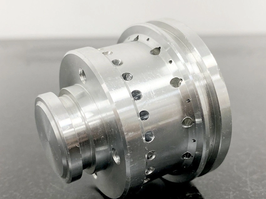
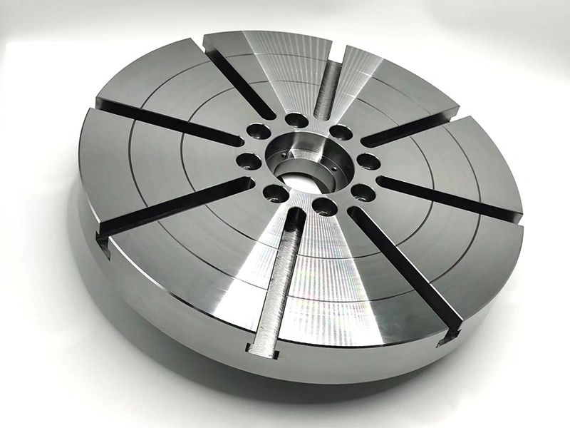
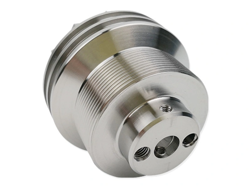
What information is needed to quote multi-axis machined parts?
What Information Is Needed to Quote Multi-Axis Machined Parts?
To quote multi-axis machined parts accurately, suppliers usually need a 3D CAD model, 2D drawing, material specification, quantity, critical features, surface finish, heat treatment requirements, inspection needs, and information about the part’s function or assembly requirements.
From an engineering perspective, a quote for multi-axis machining services requires more process review than standard CNC parts. The supplier must evaluate tool access, setup count, rotary-axis strategy, collision risk, workholding method, and the relationship between multi-side features.
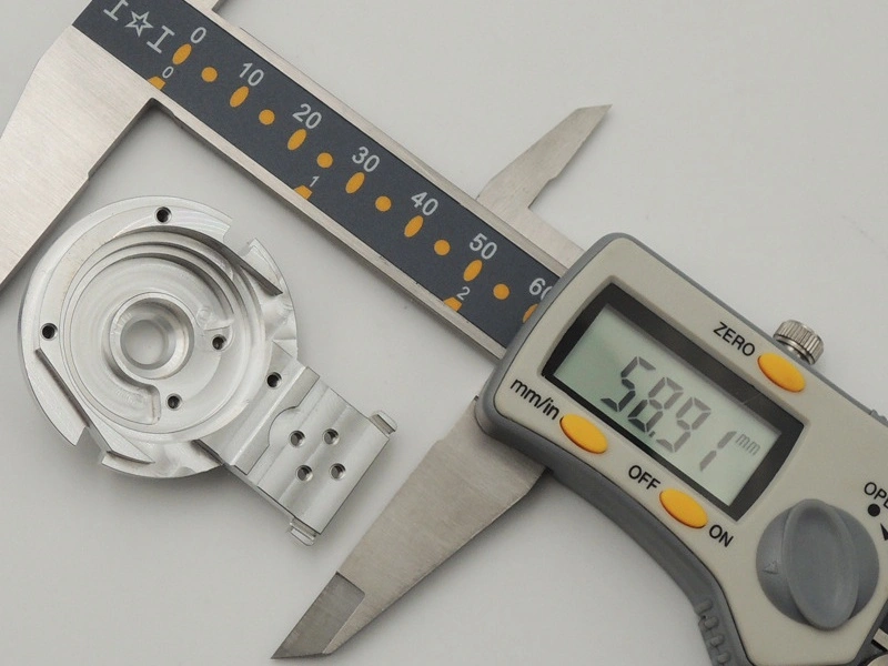
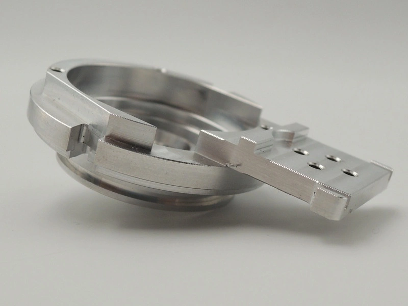
1. Key Information Needed for a Multi-Axis Machining RFQ
Required Information | Why It Matters for Multi-Axis Machining |
|---|---|
3D CAD file | Used to evaluate geometry, tool access, machining direction, rotary axis movement, and collision risk |
2D drawing | Defines tolerances, threads, GD&T, surface finish, datums, and inspection notes |
Material grade | Affects cutting strategy, tool wear, heat control, deformation risk, and cost |
Quantity | Determines setup strategy, fixture investment, programming effort, and unit cost |
Critical features | Helps identify which faces, holes, bores, or surfaces require priority control |
Surface finish | Affects finishing passes, toolpath planning, tool orientation, and post-processing needs |
Heat treatment | May require rough machining before treatment and finish machining afterward |
Inspection requirements | Determines whether CMM, FAI, dimensional reports, or surface checks are required |
Application | Helps identify functional features, assembly risks, and manufacturability concerns |
Delivery target | Helps evaluate process planning, programming time, fixture preparation, and capacity |
2. Why 3D Files Are Especially Important
Multi-axis machining depends heavily on 3D geometry because the supplier must evaluate tool direction, rotary-axis orientation, tool length, workholding clearance, collision risk, surface transitions, and whether the part can be machined in fewer setups.
For complex brackets, housings, manifolds, fixtures, and multi-side metal parts, STEP or X_T files help determine whether the part should be produced by 3-axis machining, 3+2 positioning, 4-axis machining, or more advanced multi-axis CNC machining.
3. Why 2D Drawings Are Still Required
A 3D model cannot replace a 2D drawing. The model shows geometry, but it usually does not define tolerances, thread specifications, surface roughness, GD&T, inspection datums, heat treatment notes, coating requirements, or final acceptance criteria.
For parts with angled holes, side ports, sealing faces, bearing bores, mounting pads, or datum-controlled features, the 2D drawing is essential for accurate quotation and inspection planning.
4. Critical Features Should Be Clearly Marked
Buyers should identify which features are function-critical. These may include locating holes, sealing surfaces, precision bores, angled holes, threaded ports, mounting faces, datum surfaces, and mating interfaces.
This helps the supplier decide which features need tighter process control, which datums should be machined first, and whether precision machining services are required for key dimensions and inspection control.
5. Prototype and Low-Volume Quotes Need Stage Information
If the project is still in design validation, buyers should state whether the parts are prototypes, engineering samples, low-volume production, or production-ready components. This affects fixture planning, inspection level, and cost strategy.
For early-stage complex parts, CNC machining prototyping can verify geometry, assembly fit, and tolerance feasibility before moving to repeat batches. For bridge production or small batches, low-volume manufacturing helps balance fixture cost, repeatability, and delivery stability.
6. What Can Increase a Multi-Axis Machining Quote?
Cost Driver | Reason |
|---|---|
Complex multi-side geometry | Requires more programming, toolpath simulation, and setup planning |
Tight GD&T requirements | May require controlled datums, slower finishing passes, and CMM inspection |
Difficult material | Increases tool wear, cycle time, heat control requirements, and machining risk |
Thin walls or lightweight pockets | Require careful clamping, staged machining, and deformation control |
High surface finish | May require additional finishing passes or post-processing |
Full inspection documentation | CMM reports, FAI, and dimensional reports increase inspection time and documentation work |
7. Practical Engineering Recommendation
For faster quotation, buyers should send STEP or X_T files together with PDF drawings, material grade, quantity, surface finish, heat treatment, critical feature notes, required inspection documents, and delivery target.
Neway can review the geometry, tool access, datum strategy, setup count, fixture method, inspection requirements, and production stage to determine the most suitable route for custom multi-axis machined parts.