How do you ensure bottom shape and dimensional accuracy for blind deep holes?
Blind deep-hole bottom shape and dimensional accuracy depend on a defined functional surface, a tool path that can form it, stable chip, thermal, and deflection control, and inspection from the drawing datum. A standard drill leaves a point; a flat seat, radius, cone, or custom contour needs a different finishing route. The inspection probe must reach the intended surface with known contact geometry. The RFQ should state full-diameter depth, point depth, bottom profile, corner radius, diameter, straightness, surface finish, datum, material condition, and the feature's function.
Specialized Tooling Solutions for Bottom Geometry Control
The cutter creates nominal shape, while runout, entry guidance, wear, and the final path determine conformance. Tool selection starts with the surface that controls function.
Flat Bottom Drilling Systems
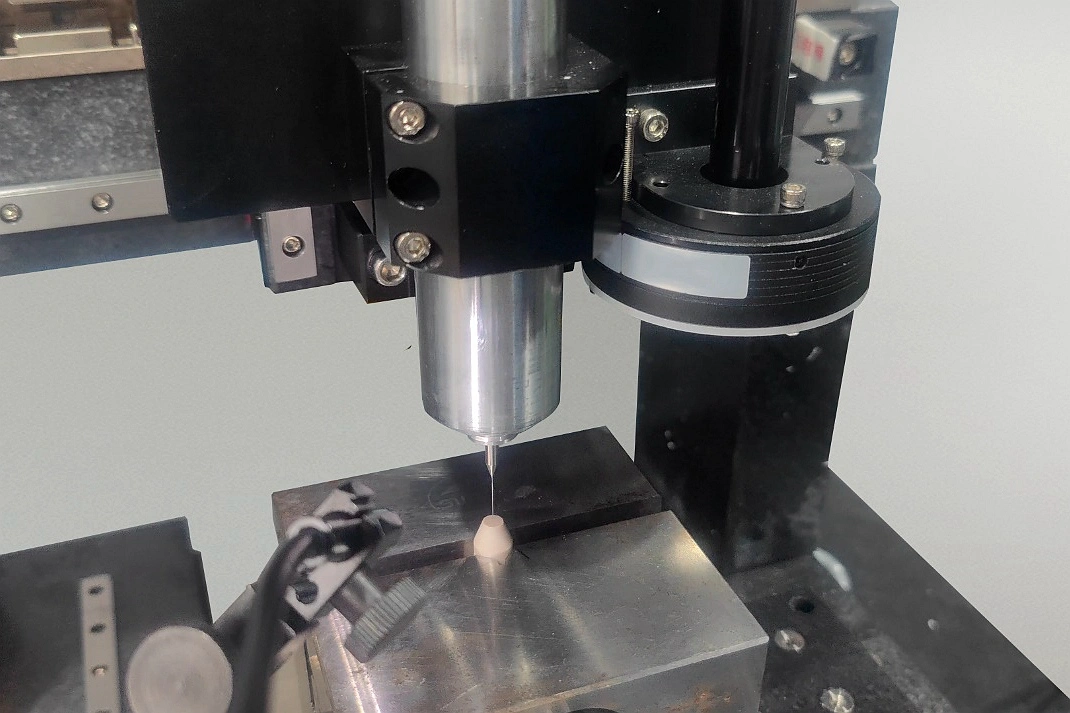
Flat-bottom tools can remove a drill point but still need a stable pilot and controlled center cutting. Aluminum 6061 can form a built-up edge, while Stainless Steel SUS303 can add heat and burr risk. Bottom flatness is separate from depth and requires an approved measurement; tool shape alone is not proof.
Contoured Bottom Tooling
A dome, cone, radius, or stepped seat requires a form tool or programmed finishing path. For Medical Device components, the drawing should identify the contact band or fluid surface that controls acceptance; maximum depth alone can miss a profile error.
Non-Conventional Machining Integration
Electrical Discharge Machining (EDM) Service can form hard or non-rotational bottom features beyond a drill's reach. The buyer must define corner condition, recast-layer requirements, finish, and inspection. EDM does not by itself prove contour accuracy.
Advanced Process Controls for Dimensional Accuracy
Blind-hole accuracy requires a guided cutting edge, an open chip path, and thermal stability through the final pass. Chips cannot leave through the far end, so evacuation becomes critical near the bottom.
Chip Evacuation Management
Chip packing can scratch the wall, alter the seat, deflect the tool, or cause breakage. Practical controls include:
Peck drilling cycles selected for depth, chip form, flute volume, and material rather than a generic retract distance
High-pressure coolant systems used only with tooling and fixturing rated for the chosen pressure and flow path
Customized cutting parameters that create evacuable chips and avoid dwell or rubbing at the blind end
Thermal Distortion Compensation
Heat can change bore size and depth. The control plan should separate cutting stability from final acceptance:
Thermal modeling used as a planning aid, with its assumptions confirmed on the actual material and cycle
Coolant temperature control coordinated with workpiece stabilization instead of treating coolant temperature as part temperature
In-process compensation kept separate from final measurement; ISO 1:2022 sets 20 degrees C as the GPS reference temperature
Tool Deflection Management
Tool bending and runout can create taper, drift, chatter, or an incorrect bottom center. Useful controls are:
Stiffness-optimized toolholders with measured runout and the shortest practical unsupported length
Progressive drilling sequences built from a qualified guide hole; TBT specifies controlled guide-hole diameter and length for single-lip drilling on machining centers
Active tool monitoring treated as an alarm input, with wear limits confirmed by measured parts rather than spindle data alone
Precision Measurement and Verification Techniques
Verification must match the characteristic: a depth gauge checks axial distance, a bore gauge checks size, and a profile method checks bottom form. One reading cannot establish all three. The plan must define access, tip radius, datum, temperature, cleanliness, and acceptance.
Non-Contact Internal Inspection
A borescope or video probe can reveal chips, burrs, scratches, burns, and incomplete cutting at the blind end. Visual evidence does not establish diameter, flatness, or contour unless the optical system is calibrated for that measurand. Replicas or computed tomography may help when access is restricted, but the method and uncertainty must fit the tolerance.
Custom Gauge Development
A dedicated depth or profile gauge can shorten production checks when its contact surface matches the drawing definition. The gauge must reference the same datum, avoid bridging a drill point, and distinguish full-diameter depth from point depth. Gauge repeatability and reproducibility should be evaluated before its result becomes an acceptance decision.
CMM with Specialized Probes
Contact CMM probing can support Precision Machining Service inspection when a qualified stylus reaches the required surfaces without excessive bending or collision. For Aerospace and Aviation parts, report the datum alignment, stylus tip, measured sections, decision rule, and inaccessible regions. A 2024 Sensors experiment (doi:10.3390/s24237847) measured a nominal 100 mm, 700 mm-deep blind bore; its test CMM reached only 300 mm. This is not a universal CMM limit. It shows why reach must be proven for the actual bore.
Material-Specific Machining Strategies
Material grade and condition change chip formation, edge wear, heat, and recovery. Tool choice and inspection frequency must reflect those differences.
Aluminum and Non-Ferrous Alloys
For Aluminum 7075 and copper alloys, check:
Built-up edge prevention because adhered material changes the center-cutting geometry and bottom finish
Surface finish optimization with sharp edges, controlled runout, and a coolant strategy compatible with the alloy
Chip welding avoidance because packed chips can score the seat and produce a false depth contact
High-Temperature Alloys
For Inconel 718 and Ti-6Al-4V (TC4), control:
Conservative cutting parameters through tool-life evidence, not a universal speed or feed value
Specialized tool geometries that cut at the center without rubbing or work-hardening the bottom
Advanced tool materials selected for grade, condition, depth, coolant delivery, and required finish
Hardened Steels
For hardened 4140 Steel and tool steels, review:
Carbide tooling for edge wear that can shift diameter, depth, and corner condition together
Reduced cutting forces where long reach or limited rigidity makes chatter more likely
Vibration damping toolholders as one control, with bottom condition still confirmed on the finished feature
Integrated Quality Assurance Framework
A defensible plan links the drawing definition to process controls and a capable measurement method. It defines pre-cut checks, intervention signals, and release evidence.
Pre-Process Validation
Before machining, confirm:
Tool runout verification at the relevant gauge length, with a limit derived from the hole requirement
Coolant pressure testing together with flow direction, filtration, and a clear chip-return path
Program simulation against tool length, holder clearance, bottom stock, and the drawing depth datum
In-Process Monitoring
During machining, review:
Torque monitoring for change from a qualified baseline, not as direct evidence of hole conformance
Acoustic emission sensors only when validated for the tool, material, machine, and failure being detected
Adaptive control systems within approved parameter limits, followed by dimensional confirmation after any intervention
Post-Process Verification
After machining, require:
Destructive analysis only on an authorized sample when inaccessible geometry cannot be validated non-destructively
Statistical process control on separately defined diameter, depth, straightness, and profile characteristics
Surface roughness measurement by a method that reaches the specified bottom zone without substituting sidewall data
Blind deep-hole quality depends on the bottom definition, tool path, process controls, and inspection method referring to the same functional surface. For Automotive, Power Generation, or industrial parts, the RFQ should identify the datum, measurand, tolerance, bottom function, material condition, inspection method, report, and any sectioned-sample permission. These inputs prevent point depth, full-diameter depth, bore size, and bottom profile from being treated as one result.