Can metal SLS make complex parts with internal cavities, and how is powder removed?
Yes, metal SLS can produce complex parts with internal cavities, but each cavity needs a continuous powder-escape path, a qualified depowdering method, and an acceptance method matched to the residual-powder risk. In buyer terminology, metal SLS usually means laser powder bed fusion of metals (PBF-LB/M), including DMLS and SLM. Unfused feedstock surrounds internal features during the build; it does not guarantee cleanability. A sealed pocket, blind branch, narrow reversal, or uninspectable lattice may be printable yet unacceptable. The RFQ should identify every enclosed volume, permitted access port, build and draining direction, cleaning sequence, residual-powder limit, and verification method before the build orientation is released.
The Capability for Unprecedented Complexity
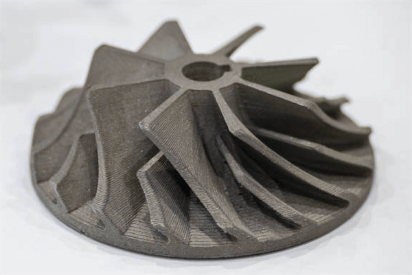
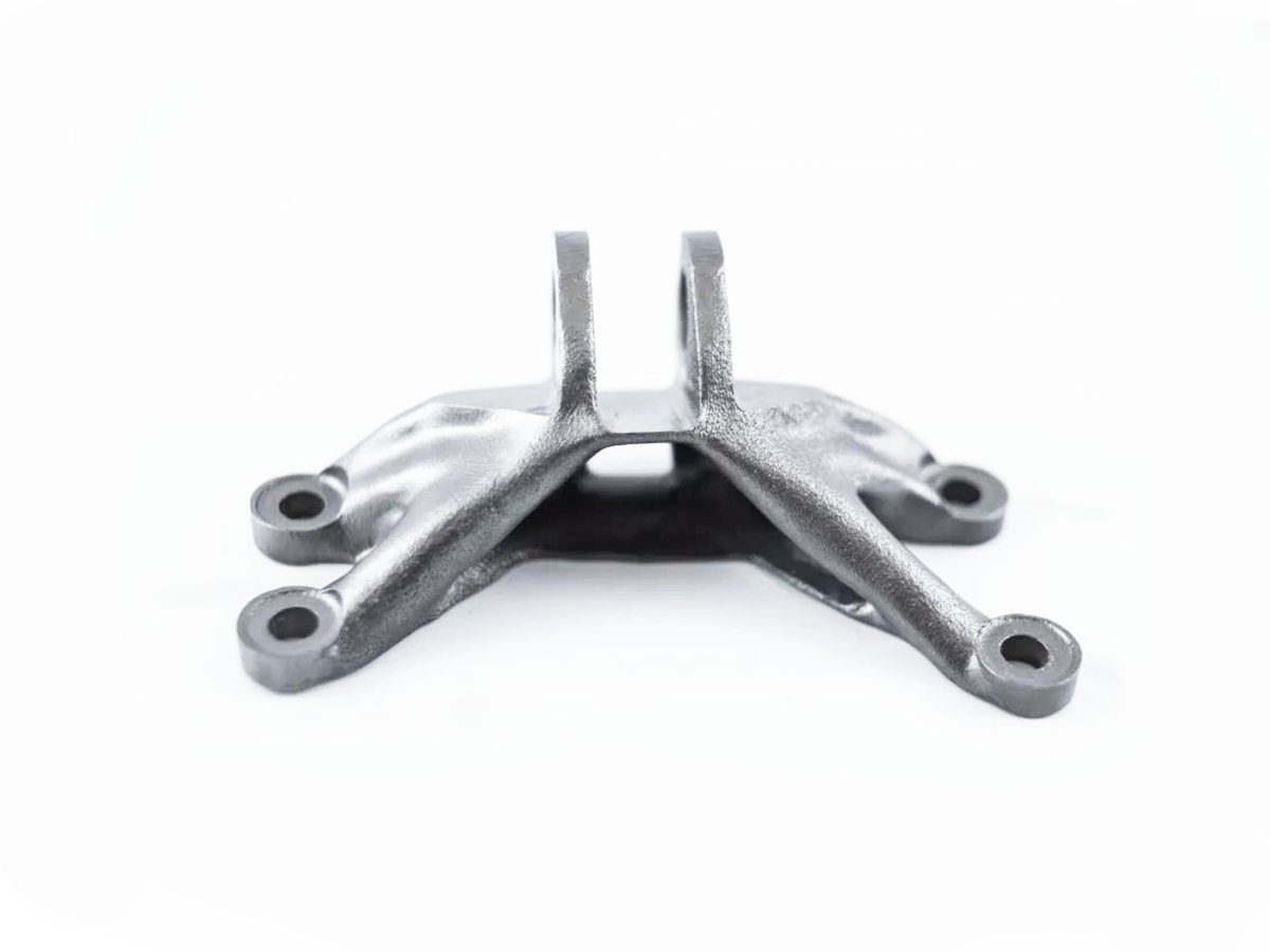
Metal SLS can create intricate internal cavities when the geometry remains drainable and inspectable. Layerwise fusion can consolidate channels, lattices, undercuts, and manifolds that would require several components or inaccessible tools in a subtractive route. Loose powder occupies surrounding space, although some metal overhangs still require fused support depending on orientation and the qualified parameter set. The as-built passage also differs from the CAD model: downskin sag, dross, adhered particles, distortion, and roughness can reduce the effective section. ISO/ASTM 52911-1:2019 provides PBF-LB/M design guidance, but a representative channel and inspection plan must qualify the actual alloy-machine-parameter combination. Typical decisions include:
Conformal Cooling Channels: In injection-molding or die-casting tooling, DMLS 3D Printing can form cooling paths that follow the working surface more closely than straight drilled bores. Approval should depend on the measured channel section, leak integrity, pressure drop, internal roughness, and residual-particle limit rather than the nominal path alone.
Lightweighting: Internal lattice structures in aerospace and aviation components can reduce structural mass, but retained powder may erase part of that benefit. Cell openings, node geometry, orientation, outlet access, and the inspection resolution should be qualified on a representative lattice before the drawing fixes a mass limit.
Fluid Flow Optimization: Consolidated manifolds can reduce joints and package complex routes for automotive and power generation systems. A smooth CAD passage does not establish as-built flow performance. The buyer should specify medium compatibility, allowable pressure drop, leak criteria, particle cleanliness, and whether internal finishing is required.
The Critical Process of Powder Removal
Powder removal succeeds only when geometry, orientation, cleaning energy, containment, and verification are planned as one manufacturing sequence. Powder can bridge across a small opening, pack behind a turn, settle in a dead leg, or remain between lattice nodes. Later heat, vibration, pressure cycling, or machining can release material that appeared stable during initial cleaning. The process therefore needs a defined endpoint, not an operator judgment that the part looks empty.
Design for Powder Removal: Each internal volume needs at least one practical outlet and usually a second opening for venting, observation, or directional flow. There is no universal minimum for powder escape holes; evacuation depends on powder size distribution and shape, alloy, passage hydraulic diameter, length, turns, junctions, internal roughness, orientation, and the available cleaning method. Ports should support more than one draining orientation and avoid isolated high or low points. If a temporary port will be plugged, welded, or machined away, the closure and final inspection belong in the original process plan.
Initial Depowdering: Bulk powder may be recovered by gravity, controlled rotation, vibration, vacuum, or compatible gas flow while the part remains on the plate or after the specified stress-relief and separation stage. The sequence must follow the qualified material and safety controls, especially for reactive or combustible metal powders. For a branched manifold, recording part orientation and recovered mass at each cycle is more useful than applying compressed gas from one convenient port and assuming every branch received flow.
Advanced Powder Removal Techniques: A difficult network may need several controlled mechanisms, but each method must reach the trapped region without damaging thin walls or adding another contaminant.
Ultrasonic Cleaning: Ultrasonic agitation can loosen particles when liquid reaches and vents from the full passage, the cleaning chemistry is compatible with the alloy, and air locks are avoided. Cavitation intensity falls in shielded or narrow regions, so an ultrasonic cycle is a process step rather than evidence that a blind branch is clean.
Vibratory Tumbling: Controlled multi-axis vibration or rotation can mobilize dry powder through accessible outlets. Conventional tumbling media may not enter a fine internal network and can lodge in openings or damage lattice struts. The fixture, frequency, orientation sequence, and stop criterion should be qualified on representative geometry.
Aggressive Methods: Line-of-sight sandblasting or accessible-flow electropolishing may change exposed roughness after bulk depowdering. Neither process proves that hidden powder has left an unobserved branch. Abrasive entrapment, dimensional change, chemistry, and later particle release require separate controls.
Verification: Evidence should match the cavity and service risk. A borescope verifies only surfaces within its access and field of view. Stable dry-mass comparison can reveal a change but may not locate residue. Flow and pressure-drop tests confirm functional passage behavior, not particle cleanliness in every pocket. X-ray computed tomography can inspect inaccessible regions when material thickness, voxel size, contrast, reconstruction, and the specified detectable residue are compatible. The drawing or purchase specification should define the method, detection limit, sampling, and inspection stage instead of requiring an unmeasurable claim of absolute cleanliness.
Engineering Guidelines and Limitations
Hole Size and Accessibility: Port diameter alone does not establish depowderability. Channel length-to-diameter ratio, bends, branches, orientation, rough downskin, lattice openings, and tool access can govern powder flow. Before releasing a minimum passage, use a representative coupon or channel built with the intended alloy, orientation, layer and contour strategy. Record the successful draining sequence and acceptance method, then preserve those conditions in production.
Risk of Trapped Powder: Closed islands, dead-end chambers, cross passages, fine lattice nodes, and abrupt section changes can retain feedstock without an external sign. Residue may increase mass, obstruct flow, alter thermal response, contaminate a downstream system, or release particles under vibration. Where the consequence is high, define an allowable residual quantity or detectable feature and reject geometry that no available method can inspect to that limit.
Post-Processing Integration: Depowdering must be sequenced with heat treatment, plate separation, internal finishing, plugging or welding, and CNC Machining. Machining can open access ports and finish sealing faces, but coolant, chips, or abrasive media can recontaminate a clean channel. Final inspection should occur after the last operation capable of closing, loading, or contaminating the passage.
Metal SLS is an appropriate route for an internal cavity only when the as-built section can meet function, all loose powder has a practical exit, and the agreed inspection can verify the acceptance limit. The RFQ should state alloy and powder system, internal-volume map, minimum passages, turns and branches, temporary and permanent ports, build and draining directions, cleaning sequence, residual-powder criterion, detection limit, flow or leak test, and downstream operations. If one cavity cannot be cleaned and verified, enlarge or reroute it, split the part for joining, add a removable access feature, or select machining, casting, or another process.