Thermal Coating Service: High Temperature Alloy Thermal Barrier Coatings (TBCs)
Introduction: Thermal Barrier Coatings for High-Temperature Alloy Parts
A thermal coating service for high-temperature alloy Thermal Barrier Coatings (TBCs) designs a layered ceramic-and-metallic system that lowers heat flow into a superalloy substrate while keeping adhesion, oxidation resistance, geometry, and inspection limits under control. A well-designed TBC can reduce metal temperature by about 100–300°C in suitable turbine or hot-gas conditions, but that range depends on coating thickness, topcoat microstructure, cooling design, gas temperature, dwell time, and bond coat condition. TBC selection should start from the component duty cycle, not from a coating name. The RFQ should state the alloy, operating temperature, thermal cycling pattern, hot-corrosion exposure, critical dimensions, coating allowance, and acceptance method.
For buyers comparing thermal coating services, the main decision is whether the supplier can connect machining, surface preparation, masking, bond coat selection, ceramic deposition, dimensional inspection, and coating validation as one controlled workflow. A TBC is not a paint layer added at the end. It changes thickness, edge build-up, hole flow area, roughness, thermal stress, and sometimes the final machining or inspection plan. The safest project route defines coating boundaries before machining is finished, so datums, mask lines, cooling holes, and post-coating checks are not treated as late corrections.
How Thermal Barrier Coatings Work: Core Functions & Mechanisms
1. Thermal Insulation: Ceramic Layers Blocking Heat Flow
TBCs reduce metal temperature because the ceramic topcoat has low thermal conductivity and a microstructure that slows heat transfer from the gas path to the alloy. Yttria-stabilized zirconia systems often fall near 1–3 W/m·K under coating-specific test conditions, but the part result also depends on thickness, porosity, cracks, sintering, cooling air, and exposure time. More thickness can improve insulation, yet it can also increase residual stress, spallation risk, and dimensional interference.
Lowers substrate temperature when coating thickness, cooling design, and service temperature are matched to the component rather than copied from another hot part.
Reduces thermal gradients and thermal fatigue by limiting heat flow into thin walls, leading edges, seal areas, and other zones that see fast heating or cooling.
Enables higher gas path temperatures only when the base alloy, cooling system, bond coat, and inspection plan can support the added thermal demand.
Coating thickness should be treated as a design variable with a tolerance, not as a “thicker is safer” rule. Thin coatings may provide too little insulation. Over-thick coatings can bridge small radii, narrow holes, change aerodynamic surfaces, and create higher stored stress during cycling. The buyer should identify no-coat areas, coating allowance, post-coating dimensions, and whether hole flow or surface profile must be verified after coating.
2. High-Temperature Oxidation & Hot Corrosion Protection
A TBC system also protects the alloy from oxidation and hot corrosion through the bond coat and the thermally grown oxide layer that forms during service. The ceramic topcoat slows heat transfer, but the metallic bond coat helps control oxygen transport and chemical attack. If contaminants from fuel, air, salts, sulfates, vanadates, or process gas are present, the coating design must address chemistry as well as temperature.
High-temperature oxidation of nickel and cobalt-based alloys can accelerate when the bond coat is too thin, chemically mismatched, contaminated, or damaged during preparation.
Attack from corrosive species such as sulfates, vanadates, or contaminants in fuel and air can shorten coating life even when thermal insulation appears adequate.
Microstructural degradation may include TGO growth, interface cracking, sintering of the topcoat, and loss of strain tolerance during repeated thermal cycles.
For critical superalloy components, the practical question is not whether a ceramic layer can survive heat in isolation. The question is whether the whole stack can survive temperature, chemistry, erosion, vibration, and inspection requirements at the same time. A buyer should share fuel type, atmosphere, duty cycle, cleaning method, and expected inspection interval before choosing a TBC route.
Layered System Design: Each Layer Has a Job
Ceramic Topcoat: The Thermal Barrier Itself
The ceramic topcoat is usually the visible layer, but its job is more specific than resisting heat. It must provide insulation, tolerate strain, keep a stable phase structure, and avoid premature spallation at edges, holes, and high-gradient zones. The topcoat microstructure is shaped by the deposition process. APS tends to form a lamellar structure with pores and microcracks, while EB-PVD forms a columnar structure that can bend with thermal strain.
Low thermal conductivity is useful only when the coating thickness and porosity do not create unacceptable stress, edge build-up, or blocked features.
Phase stability under operating temperature must be judged against peak temperature, dwell time, thermal cycling, and possible sintering during service.
Thermal expansion compatibility with underlying layers reduces interface stress, especially where the alloy, bond coat, and ceramic expand differently.
Porosity and microcracking provide strain tolerance and thermal shock resistance, but too much porosity can reduce erosion resistance and coating cohesion.
Bond Coat: The Functional Bridge to the Substrate
Between ceramic and metal lies a metallic bond coat, often MCrAlY where M may be Ni, Co, or Ni/Co. The bond coat is the functional bridge between the ceramic and the alloy. It must adhere to the substrate, feed a controlled alumina scale during service, and limit oxidation or corrosion without creating harmful diffusion or brittle interface behavior.
Provides adhesion for the ceramic topcoat only when the surface is clean, roughness is controlled, and the bond coat is compatible with the substrate.
Forms a stable Al2O3 thermally grown oxide layer; excessive TGO growth can become a crack path and drive topcoat spallation.
Acts as a chemical and oxidation barrier protecting the base alloy while still allowing the full coating system to tolerate thermal cycling.
Bond coat chemistry and thickness must be matched to alloys such as Inconel 625, Hastelloy X, and Rene 41. The same ceramic topcoat can behave differently on these substrates because alloy chemistry, heat treatment, strength level, oxide formation, and service temperature are not identical. A useful RFQ names the alloy grade and condition, not only “nickel alloy” or “superalloy.”
Key Process I: Atmospheric Plasma Spraying (APS)
Process Features
Atmospheric Plasma Spraying is one of the most common TBC deposition methods for industrial and turbine hardware. Powder feedstock is heated in a plasma jet and propelled onto a prepared substrate, where splats build a lamellar ceramic layer. The coating result depends on powder size, torch power, stand-off distance, robot path, part temperature, surface roughness, and masking. APS can cover complex shapes, but edges, deep pockets, holes, and shadowed areas still need process review before quoting.
Uniform coating thickness over complex geometries requires controlled gun path, fixture access, masking, and allowance for edge build-up or overspray.
Fine-tuned porosity and lamellar microstructure can improve insulation and strain tolerance, but process settings must also consider erosion, thermal cycling, and adhesion.
Repeatable quality for single parts and mass production depends on documented parameters, witness samples, batch traceability, and inspection frequency.
Typical Applications & Performance
Gas turbine blades and vanes, combustor components, and transition pieces often use APS when coating thickness, repairability, and cost balance are more important than a very smooth gas-washed surface.
Industrial burner and furnace components, hot-gas ducts, fixtures, and shields may use APS when thermal insulation, oxidation protection, and rebuild-friendly processing are required.
APS is often selected when a buyer needs a practical TBC route for thicker coatings, larger parts, or refurbishment. The decision should still check whether the lamellar structure is acceptable for the duty cycle. If the component sees high thermal shock, erosion, or tight aerodynamic requirements, APS may need extra validation or a comparison with EB-PVD.
Key Process II: Electron Beam PVD (EB-PVD)
Unique Columnar Microstructure
EB-PVD forms a ceramic coating in high vacuum by evaporating ceramic material with an electron beam and condensing it onto the component. The result is a columnar microstructure that can accommodate thermal strain better than many dense coatings. EB-PVD is not chosen only because it sounds more advanced. It is chosen when the part geometry, cost, coating thickness, surface finish, and thermal-cycle demand justify the process.
Absorbs thermal strain extremely well because columnar gaps allow the ceramic to move during heating and cooling without immediately cracking across the interface.
Provides outstanding thermal shock resistance when bond coat condition, topcoat thickness, and cooling design are matched to the engine or turbine duty cycle.
Delivers smooth gas-washed surfaces that can help aero-engine aerodynamics, but masking, line-of-sight access, and geometry still constrain coverage.
High-End Aerospace Applications
EB-PVD TBCs are widely used on single-crystal turbine blades and vanes in aerospace engines, where durability, cooling efficiency, surface condition, and repeatable traceability all matter. A buyer should confirm whether the program requires a specific coating specification, witness coupon plan, repair approval, or special-process qualification. If the drawing already defines EB-PVD, substituting APS is not a simple cost decision because the microstructure and strain response differ.
Coating Materials: From Classic YSZ to Next-Generation Ceramics
Yttria-Stabilized Zirconia (YSZ)
7–8 wt% YSZ remains a common TBC ceramic because it balances low thermal conductivity, thermal expansion behavior, phase stability, and process familiarity. It is still not universal. Long exposure at high temperature can sinter the structure, reduce strain tolerance, and change thermal conductivity. The buyer should state peak temperature, dwell time, thermal cycles, erosion exposure, and whether coating repair is expected during the part life.
Low thermal conductivity helps reduce metal temperature, but the final part result depends on coating thickness, porosity, cooling design, and service environment.
Good phase stability in service temperature ranges must be tied to the actual duty cycle, not only a material data sheet value.
Compatible thermal expansion with Ni-based superalloys helps reduce mismatch stress when the bond coat, substrate, and heat treatment are correctly selected.
Advanced Rare-Earth Ceramics
Rare-earth zirconates and other advanced ceramics may be considered when standard YSZ does not provide enough temperature capability or phase stability. These materials can offer lower conductivity or better high-temperature stability, but they may bring trade-offs in toughness, processing window, cost, erosion resistance, or compatibility with the bond coat. For power generation and next-generation turbine work, the material choice should be validated with representative thermal cycling and inspection rather than selected only from a property comparison.
Quality Assurance: Validating TBC Reliability
Thickness, Adhesion & Microstructure
A TBC should be accepted only after inspection confirms that the coating is the right thickness, bonded to the prepared substrate, and free from defects that change function. Inspection is not just a final paperwork step. It is how the buyer confirms that the coating system can survive the intended environment and that the coating did not block holes, overload edges, or move critical dimensions.
Ultrasonic or eddy-current thickness measurements, plus metallographic cross-sections, can confirm whether the coating thickness and layer structure match the specification and critical zones.
Adhesion or bond strength tests may use project-specific requirements; a screening value such as 30 MPa only makes sense when the coating type, specimen geometry, and test method match the specification.
Microstructure evaluation should review lamellae, porosity, TGO growth, interface condition, cracks, contamination, and columnar morphology for EB-PVD coatings.
Thermal Cycling & Lifetime Testing
Thermal cycling and thermal shock testing are useful because many TBC failures occur after repeated expansion, contraction, oxide growth, and cooling-air interaction, not during the first heat exposure. Test conditions should define peak temperature, dwell time, ramp rate, cooling method, atmosphere, and inspection interval. A generic furnace cycle may be too mild for a combustor part or too severe for a steady industrial shield.
TGO growth and cracking show that oxidation and interface stress are consuming coating life, even before large areas of ceramic are missing.
Topcoat spallation indicates that strain, oxidation, contamination, erosion, or poor bond-coat condition has exceeded the coating system’s tolerance.
Interface degradation can come from preparation damage, coating chemistry, repeated cycling, hot corrosion, or incompatible repair history.
Core Application Fields
Aerospace Engines
TBCs are applied to hot-section components when alloy strength, cooling design, and coating durability must work together under severe thermal cycling. Common target parts include:
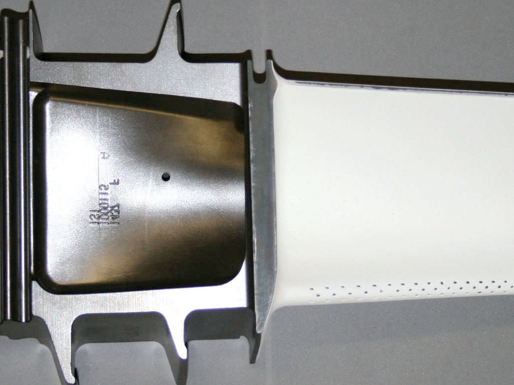
Turbine blades and vanes where coating thickness, cooling holes, and aerodynamic surface quality must be controlled together.
Combustor liners, transition ducts, and shrouds that need oxidation protection, thermal insulation, and resistance to cyclic heat exposure.
Nozzles and aftertreatment hot parts where hot gas chemistry, erosion, and dimensional limits can make coating selection more difficult.
For components in Inconel 718 and similar alloys, the buyer should confirm alloy condition, service temperature, coating allowance, and post-coating inspection before approving a coating route. Inconel 718 has useful high-temperature strength, but its heat treatment, aging condition, and operating temperature limit still matter. A TBC cannot turn an unsuitable alloy condition into an acceptable hot-section design.
Power Generation & Industrial Systems
In stationary gas turbines and high-temperature process equipment, TBCs are often evaluated by operating cost, inspection interval, fuel chemistry, repairability, and downtime risk. The coating must protect the part without making maintenance harder.
Increase turbine efficiency when the turbine design, cooling system, and material limits allow higher thermal loading without sacrificing inspection safety.
Extend inspection intervals only when coating life is validated against actual cycling, contaminants, erosion, and repair conditions.
Protect critical hot gas parts in chemical, metallurgical, and thermal processing equipment where oxidation, corrosion, and thermal gradients drive damage.
Key Design Considerations Before Applying TBCs
1. Substrate & Bond Coat Compatibility
Substrate and bond-coat compatibility should be reviewed before machining is finalized, because coating can change final dimensions and expose preparation-sensitive areas. The design review should include:
Alloy composition and prior heat treatment, including whether the substrate can tolerate cleaning, blasting, coating temperature, and any repair cycle.
Operating temperature window and duty cycle, especially peak temperature, dwell time, ramp rate, and number of expected thermal cycles.
Oxidation and hot-corrosion resistance of the substrate and bond coat system under the actual atmosphere, fuel quality, and contaminant exposure.
2. Service Environment & Load Profile
The service environment decides whether insulation, oxidation resistance, erosion resistance, strain tolerance, or repairability should dominate the coating choice. The coating design should be tuned for:
Peak and cyclic temperature, including whether the part sees rapid starts, shutdowns, quenching, or long steady dwell at temperature.
Gas composition, including fuel impurities, corrosive species, salt, sulfur, vanadium, process vapors, and cleaning residues.
Mechanical loads, vibration, erosion, and FOD risk that can turn a thermally stable coating into a mechanically damaged coating.
For oil & gas and nuclear applications, the coating review may need extra controls for corrosion chemistry, cleaning compatibility, radiation-related constraints, documentation, and traceability. These requirements should be identified before quoting because they affect coating choice, inspection records, and release documentation.
Integrated TBC Workflow: From Machined Blank to Coated Component
A high-temperature TBC project works best when the machining and coating plan are connected before the blank is finished. The supplier workflow should define which features are machined before coating, which surfaces are masked, which datums control inspection, and which dimensions are checked after coating.
Precision CNC machining of superalloys, titanium, and heat-resistant steels should consider coating allowance, masking access, and post-coating datum strategy.
Engineered surface preparation: blasting, masking, cleanliness, and roughness control should protect critical bores, threaded features, sealing faces, and cooling holes.
Application-specific TBC systems via APS and EB-PVD should be selected from coating thickness, microstructure, strain tolerance, surface finish, geometry access, and service conditions.
Metallurgical testing, dimensional inspection, and lifetime evaluation should confirm layer thickness, interface quality, critical dimensions, coating defects, and thermal-cycle behavior.
A mass production plan should define process windows, coupon rules, inspection sampling, traceability fields, repair limits, and stop points before repeated lots begin.
The best TBC decision is a controlled engineering trade-off: APS or EB-PVD, YSZ or advanced ceramic, thicker or thinner topcoat, repairable or replace-only, and production-ready or prototype validation first. Buyers can reduce quoting risk by sending drawings, alloy condition, temperature profile, atmosphere, critical dimensions, no-coat areas, inspection standards, and expected service life with the first RFQ.
FAQ
How much can a well-designed TBC reduce metal temperature in turbines?
What is the typical service life of TBCs in real engine or turbine conditions?
What are common TBC failure modes and how can design and process reduce them?
What surface prep steps are needed before applying a reliable TBC system?
Can damaged TBCs be removed and reapplied without harming the base part?