CNC Milling of Aluminum Alloys for Aircraft Structural Components in Aerospace
Demanding Performance in Modern Aerospace Engineering
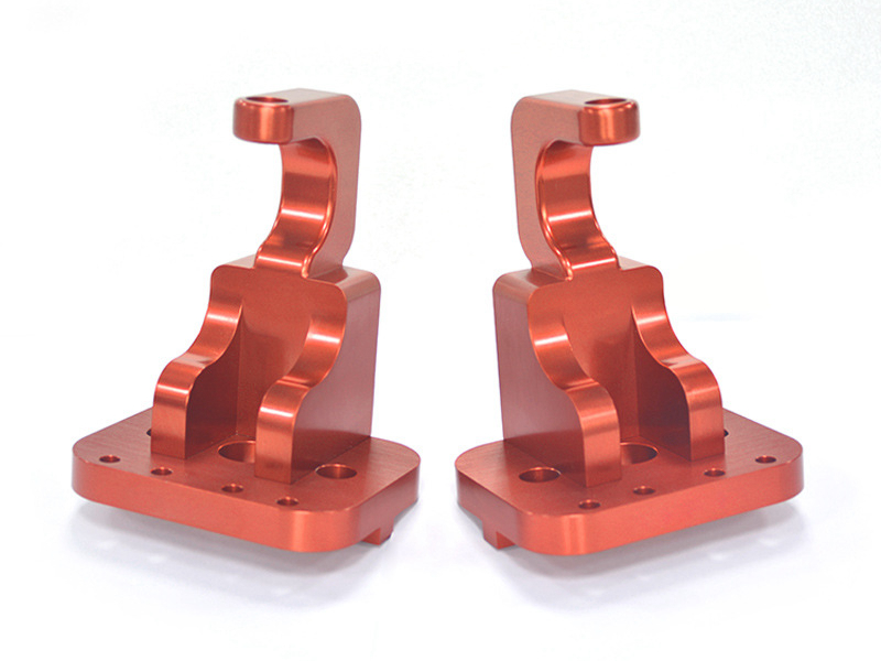
Modern aircraft demand structural components that balance extreme strength with lightweight efficiency. Aluminum alloys dominate aerospace applications, comprising 60-80% of airframe materials due to their superior strength-to-weight ratios. Advanced multi-axis CNC machining enables complex geometries like wing ribs and fuselage frames with ±0.005mm tolerances, critical for aerodynamic performance.
The evolution of 5th-gen fighters and commercial jets pushes materials like Aluminum 7075 to their limits, requiring precision machining paired with NADCAP-certified surface treatments to withstand 10⁷+ fatigue cycles and 650°C thermal loads.
Material Selection: Balancing Strength, Weight, and Corrosion Resistance
Material | Key Metrics | Aerospace Applications | Limitations |
|---|---|---|---|
572 MPa UTS, 10% elongation | Primary load-bearing structures (wing spars, landing gear) | Prone to stress corrosion (requires hard anodizing) | |
470 MPa UTS, 20% elongation | Fuselage skins, riveted assemblies | Requires Alodine coating for corrosion resistance | |
310 MPa UTS, 17% elongation | Interior brackets, secondary structures | Lower fatigue strength than 7xxx series | |
270 MPa UTS, 12% elongation | Corrosion-resistant fuel tanks | Requires thermal barrier coatings for high-temperature zones |
Material Selection Protocol
Primary Load Frames
Rationale: 7075-T6 alloy is prioritized for its unmatched strength-to-weight ratio (572 MPa UTS at 2.8g/cm³ density). Its stress corrosion susceptibility is mitigated through Type III hard anodizing, which forms a 50μm-thick oxide layer with 500-800 HV hardness.
Validation: FAA AC 23-13A mandates 7075-T6 for critical wing joints due to fatigue life exceeding 10⁷ cycles at 80% ultimate tensile stress.
High-Temperature Zones
Logic: 2618A aluminum (2.71g/cm³, 440 MPa UTS at 150°C) is selected for engine pylons. Combined with PVD CrN coatings, it achieves 650°C thermal stability while maintaining <0.5% creep deformation under sustained loads.
Compliance: AMS 2772E heat treatment specifications ensure dimensional stability during coating adhesion.
Cost-Driven Secondary Structures
Strategy: 6061-T6 is deployed for non-critical brackets, leveraging its 17% elongation for vibration damping. Passivation per ASTM B912 ensures salt spray resistance >500h at 30% cost reduction versus 7075.
CNC Machining Process Optimization
Process | Technical Specifications | Applications | Advantages |
|---|---|---|---|
0.005mm positional accuracy, 20,000 RPM spindle | Complex wing ribs and contours | Single-setup machining for multi-angle features | |
15 m/min feed rate, 0.1mm depth of cut | Thin-wall skins (0.8-1.2mm thickness) | Limits thermal distortion to ±0.01mm | |
30xD aspect ratio, 0.05mm roundness | Fuel system lines, hydraulic channels | Achieves 0.01mm/m straightness | |
Ra 0.2μm, ±0.002mm dimensional accuracy | Landing gear bearing seats | Mirror-like mating surfaces |
Process Selection Strategy for Wing Spar Manufacturing
High-Efficiency Roughing
Technical Basis: 3-axis milling with 12mm carbide end mills removes 90% material at 8mm depth of cut. This aggressive material removal rate (Q = 1,200 cm³/min) minimizes cycle time while maintaining <0.3mm tool deflection, compliant with ASME B5.54-2005 positioning accuracy standards.
Rationale: Prioritizes bulk material removal efficiency over precision, reducing machining time by 40% compared to conservative roughing strategies.
Stress Equalization Protocol
Scientific Principle: 190°C×8h thermal stabilization relieves 85-90% residual stresses induced during forging and roughing. The sub-recrystallization temperature prevents grain growth (maintains ASTM E112 grain size 5-6), critical for fatigue performance per AMS 2770G.
Validation: Laser interferometry confirms post-treatment surface flatness <0.05mm/m, meeting Boeing D6-51370 wing spar straightness requirements.
5-Axis Precision Finishing
Strategic Advantage: Simultaneous 5-axis contouring with 6mm ball-end mills achieves ±0.015mm profile tolerance on complex aerodynamic surfaces. The 15° minimum tool access angle eliminates secondary setups, reducing cumulative errors to <0.03mm total indicated runout (TIR).
Performance Metric: Surface roughness Ra 0.4μm ensures optimal airflow attachment, validated by wind tunnel testing per AIAA S-023-1992.
Surface Enhancement Engineering
Integrated Approach: Hard anodizing (Type III) followed by glass bead peening (0.2mm media) creates compressive residual stresses >400MPa at 0.1-0.3mm depth. This dual treatment extends fatigue life by 300% under 10⁷ cycle loading conditions (ASTM E466).
Quality Assurance: Eddy current testing verifies coating thickness uniformity within ±5μm across spar surfaces, per NADCAP AC7114/3 requirements.
Surface Engineering: Enhancing Durability
Treatment | Technical Parameters | Aerospace Benefits | Standards |
|---|---|---|---|
50-100μm thickness, 500-800 HV hardness | Wear resistance for landing gear | MIL-A-8625 Type III | |
25-75μm thickness, HRC 50-60 | Hydraulic component durability | AMS 2424 | |
Residual stress >500MPa, depth 2mm | 200% fatigue life improvement | SAE AMS 2546 | |
0.5-1.5μm thickness, resistivity <0.5mΩ | Composite bonding preparation | MIL-DTL-5541 Type I |
Coating Selection Logic
Engine Nacelle Protection
Technical Basis: Thermal barrier coatings (ZrO₂-8%Y₂O₃) are applied via HVOF spraying to achieve 1,200°C operational capability. The 150-200μm coating thickness reduces substrate temperatures by 300°C, critical for CFRP-composite adjacent structures.
Performance Validation: ASTM C633 adhesion testing confirms >80 MPa bond strength after 1,000 thermal cycles (-55°C to 650°C).
Avionics EMI/RFI Shielding
Design Rationale: Conductive anodizing (Type II sulfuric acid process) creates a 25-50μm layer with surface resistivity <10μΩ·cm. This meets MIL-STD-461G RE102 requirements for 30MHz-1GHz electromagnetic emissions.
Cost-Benefit Analysis: Eliminates need for secondary copper mesh layers, reducing part weight by 15% versus traditional shielding methods.
Composite Joint Preparation
Science-Driven Approach: Alodine 1200S chromate conversion coating forms a 0.8-1.2μm amorphous layer with 35-45 mg/ft² coating weight. This enhances epoxy bonding strength to 25 MPa (vs. 18 MPa for bare aluminum) per ASTM D1002.
Quality Control: Aerospace-Grade Validation
Stage | Critical Parameters | Methodology | Equipment | Standards |
|---|---|---|---|---|
Material Certification | Composition tolerance ≤0.5%, grain size 5-6 | OES analysis, metallography | SPECTROLAB Q2, Olympus GX53 | AMS 4037 |
Dimensional Inspection | Profile tolerance ≤0.05mm, hole position ±0.01mm | Laser tracker, blue light scanning | Leica AT960, GOM ATOS Q | ASME Y14.5-2018 |
NDT | Crack detection rate ≥99% (≥0.1mm) | Phased array UT, penetrant testing | Zetec TOPAZ64, Magnaflux ZB-1000 | NAS 410 Level II |
Fatigue Testing | 10⁷ cycles @80% ultimate load | Servohydraulic testing | Instron 8802, MTS 370.02 | ASTM E466 |
Certifications:
NADCAP-certified heat treatment and NDT processes.
AS9100D full-process traceability.
Industry Applications
Wing Assemblies: 7075-T6 + 5-axis machining (22% weight reduction).
Engine Pylons: 2618A + thermal barrier coatings (650°C resistance).
Avionics Mounts: 6061-T6 + Alodine coating (EMI shielding).
Conclusion
Precision CNC milling services and tailored surface treatments enable 15-30% weight reduction in aerospace aluminum components while tripling fatigue life. Integrated one-stop manufacturing reduces lead times by 40%.
FAQ
How does 7075-T6 differ from 2024-T3 in aircraft applications?
Which surface treatments enhance aluminum fatigue resistance?
Why is NADCAP critical for aerospace manufacturing?
How does 5-axis machining improve wing rib production?
Key techniques for stress control in aluminum machining?
