What CNC Machined Parts Are Most Common in Oil and Gas Equipment?
What CNC Machined Parts Are Most Common in Oil and Gas Equipment?
The most common Oil and gas equipment components produced by computer numerical control (CNC) machining, or CNC machined parts, are valve bodies and trim, threaded connectors and adapters, seal carriers and glands, bushings and wear sleeves, and housings or manifolds. The mix depends on upstream, midstream, or downstream duty, service medium, pressure, temperature, and corrosion or erosion risk.
Classify each part by its functional interface. Pressure walls, flow-control profiles, threads, seal grooves, bearing bores, and intersecting ports create different failure modes. CNC turning suits concentric diameters, shoulders, grooves, and many threads; milled ports or cross holes require another operation. The buyer should identify the critical interface, datum relationship, service specification, and release evidence.
1. Valve Bodies and Trim: Separate Pressure Boundaries from Flow-Control Interfaces
Valve bodies and trim such as stems, seats, plugs, and cages are common because oil and gas systems isolate, regulate, or redirect flow. A body may contain pressure walls, flange faces, threaded ports, and intersecting passages, while trim controls movement through seats, stems, and guiding diameters. Insufficient wall can threaten containment; a damaged seat or misaligned stem can prevent shutoff.
The drawing should distinguish pressure-containing geometry from replaceable trim and define the datum path between mating features. Machining can control a specified bore, face, thread, or profile, but it does not certify a valve pressure rating. Before release, confirm the product specification, material condition, required examination or pressure test, and dimensions supporting assembly versus sealing.
Part Family | Critical Machined Interface | Buyer Confirmation |
|---|---|---|
Valve body and trim | Pressure wall, seat, stem guide, or port relationship | Separate containment, control, assembly requirements |
Connector or adapter | Thread, shoulder, cone, face, or seal land | State connection specification and gauge |
Seal carrier or gland | Groove, lead-in edge, face, and mating diameter | State seal, installation state, surface criteria |
Bushing or wear sleeve | Bore, outside diameter, face, and lubrication path | State shaft fit, load, media, wear allowance |
Housing or manifold | Datum face, bore, port position, and remaining wall | State port relationships and inspection access |
2. Connectors and Adapters: Define Threads, Shoulders, and Sealing Geometry Together
Threaded adapters, couplings, fitting bodies, sleeves, and instrument connectors are common wherever tubing, piping, valves, or sensors meet. Their function is defined by a connection system, not thread size alone. Shoulders, tapers, sealing cones, face seals, and thread runouts may work together. A thread can pass a general gauge while the assembled connection has wrong stand-off, damaged sealing geometry, or shoulder interference.
Buyers should state the connection specification, mating component, gauge type, coating condition, and inspection state. Burrs at cross holes and incomplete thread roots need criteria. For replacement hardware, include the controlled revision or approved interface drawing; a worn field sample should not become the definition.
3. Seal Carriers and Glands: Treat Grooves, Faces, and Edges as One Interface
Seal carriers, glands, retainers, support rings, and machined seal pockets are common because static and dynamic seals need controlled geometry. Groove width and depth are only part of the interface. Mating diameter, face runout, lead-in form, edge condition, and surface texture affect seal compression and installation damage. Burrs can cause leakage or wear.
The request for quotation (RFQ) should name the seal type and material, mating part, installation direction, service medium, temperature basis, and final surface condition. Tie surface texture to the functional area and measurement method instead of one value for every face. If coating, cladding, or lapping changes a sealing feature, state whether the limit applies before or after that operation. Machining evidence is separate from a required leak or pressure test.
4. Bushings and Wear Sleeves: Match Bore Geometry to Shaft, Load, and Media
Bushings, guide sleeves, bearing sleeves, and replaceable wear liners are common in pumps, valves, actuators, and rotating or reciprocating assemblies. Their working geometry combines bore size, form, outside fit, face relationship, and lubrication features. A nominally correct bore can bind a shaft when form error, press-fit distortion, debris, or an incorrect datum removes clearance.
Material choice follows the contact pair and environment. Bronze, stainless steel, hardened steel, or another alloy is appropriate only after considering shaft material, load, speed, lubrication, abrasive solids, corrosion, and replacement strategy. Buyers should define the assembled fit at operating temperature and identify finishing after installation, such as line boring or honing. Measure the feature in the condition used for the fit decision.
Service Condition | Dominant Risk | Evidence Before Release |
|---|---|---|
Pressure-containing duty | Wall loss, discontinuity, or an incorrect sealing interface | Material identity, critical geometry, and specified test records |
H2S-containing production service | Material or condition outside the specified sour-service boundary | Specified grade, heat treatment, hardness, and traceability records |
Abrasive or erosive flow | Accelerated loss at restrictions, turns, seats, or exposed edges | Material condition, protected geometry, and surface evidence |
Repeated field maintenance | Interface damage, mixed revisions, or assembly mismatch | Controlled revision, interface checks, marking, and release records |
5. Housings and Manifolds: Control Port Relationships and Remaining Wall
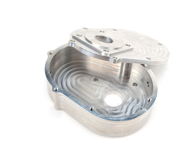
Housings and manifolds locate components, route flow, support seals, or protect instruments. Their risk often lies between features. A bore or port may meet size requirements while its position leaves inadequate wall, breaks into the wrong passage, misaligns a seal, or prevents a fitting from seating. Deep bores and intersecting holes can retain chips or hidden burrs.
A useful drawing establishes functional datums, port relationships, minimum wall where required, and access for hidden features. The supplier should connect roughing, specified stress relief, finish machining, deburring, cleaning, and final inspection so later operations do not invalidate measurements. Buyers should identify plugged passages and cleanliness criteria. Use separate checks for geometry and cleanliness.
6. Service Conditions Decide Which Part Families Dominate
Upstream well equipment may emphasize pressure-containing valve parts, threaded connections, wear components, and corrosion-resistant interfaces. Midstream systems often add pipeline valve bodies, flanges, manifolds, meter housings, and instrument connections. Downstream equipment may involve pump, compressor, process-valve, and analyzer components exposed to different fluids and temperatures. The purchase specification must define the actual duty.
International Organization for Standardization (ISO) 15156, also published as NACE MR0175, addresses material selection for hydrogen sulfide (H2S)-containing oil and gas production environments; it is not blanket approval for every component. American Petroleum Institute (API) 6A or API 6D governs corresponding wellhead/tree equipment or pipeline valves only when the order invokes that scope and edition. Identify the applicable document, any specified level or class, material limits, and validation records. Do not infer a standard from the industry label.
7. Classify the Part Before Quotation Release
Before release, classify the component as a valve pressure boundary or trim part, connector, seal carrier, wear part, housing, manifold, or documented combination. Mark the critical interface, credible failure, service condition, and acceptance evidence. This exposes missing information before the difficult work reaches a seal land, controlled thread, intersecting passage, or final-condition bore.
For oil and gas sourcing, provide the material specification and condition, controlled drawing revision, service medium, pressure and temperature basis, applicable standard and edition, critical datums and interfaces, final finish state, inspection methods, traceability, and release documents. Use CNC machining and CNC turning for defined geometry. Process choice does not replace material qualification, design verification, pressure testing, or system validation.