Nitrided Crankshaft Manufacturing and Inspection Case Review
Nitrided Crankshaft Manufacturing and Inspection Case Review
This power-generation project involved a custom nitrided alloy-steel crankshaft whose journals, crankpins, treated surfaces, and inspection records had to be managed through one connected manufacturing route. The engineering challenge was not limited to cutting a complex shape. Material identification, datum continuity, staged stock removal, nitriding, conditional follow grinding, and document handovers all influenced later work. The route defined the design controls for those interfaces, and the project's written exchanges captured the material and treatment clarifications that were actually agreed.
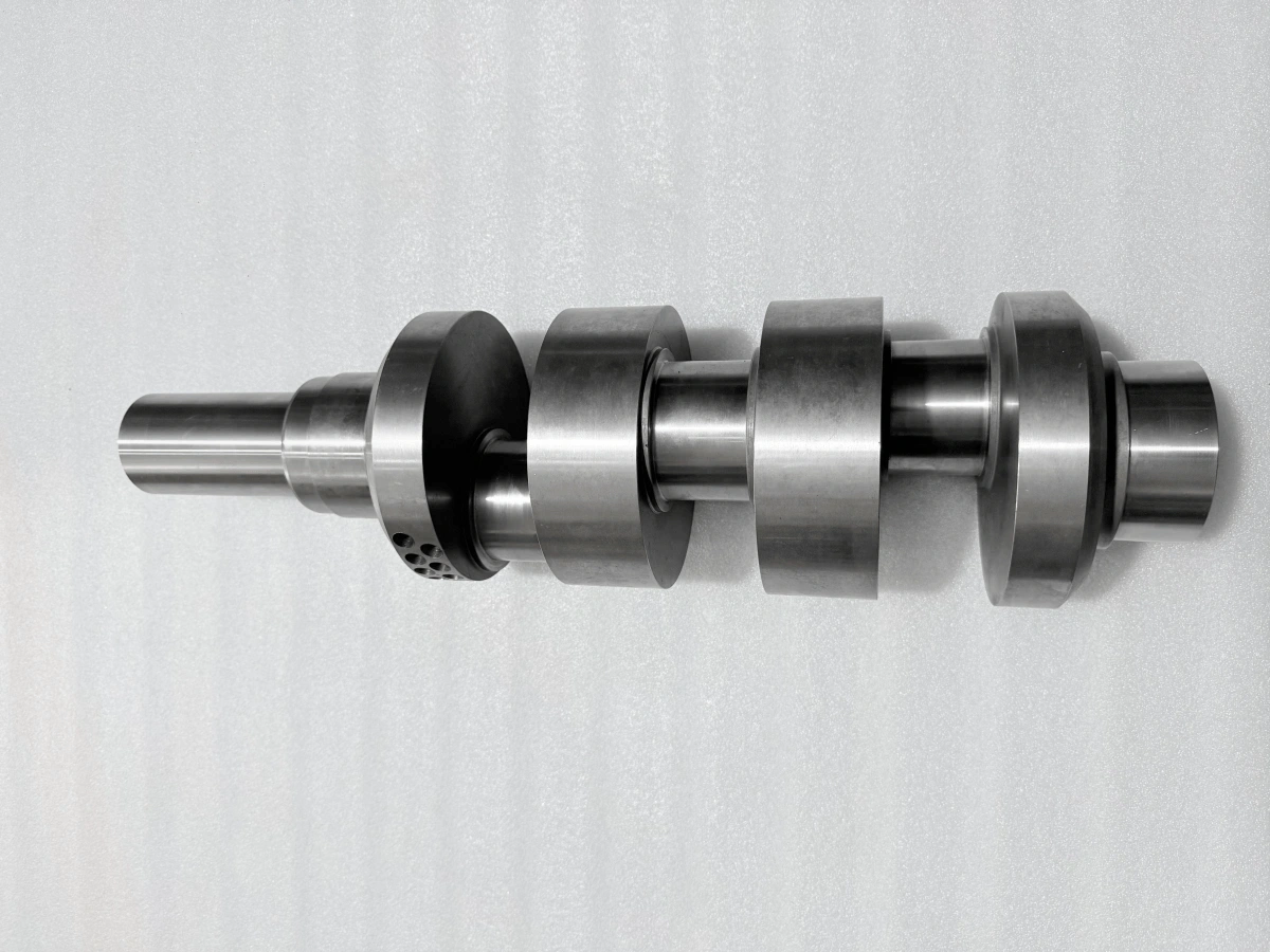
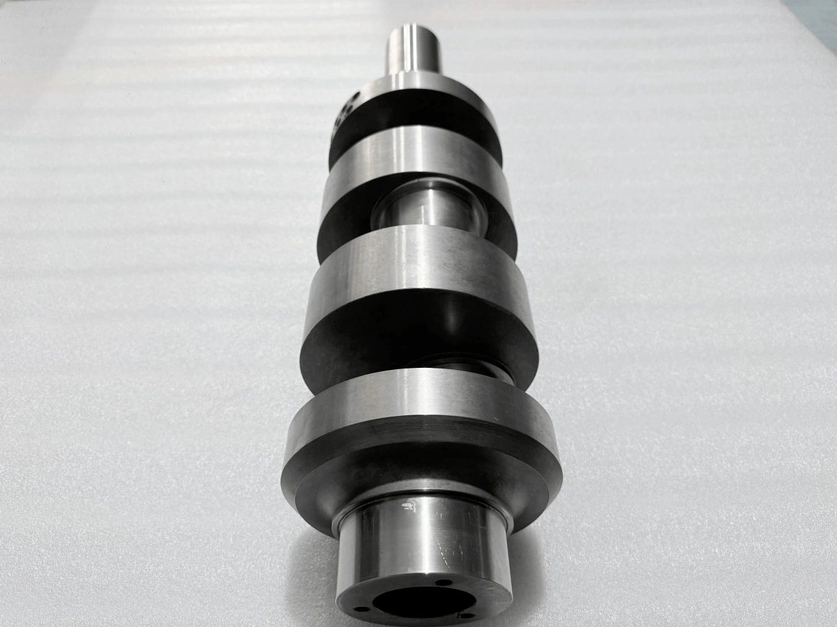
In this crankshaft CNC machining case study, we focus on the handovers that connect machining, treatment, and inspection. A planned handover should define the incoming part state, reference scheme, remaining stock, and required record. On this order, the material review and nitriding discussion produced written decisions that the manufacturing route could carry forward into subsequent instructions.
Power-Generation Crankshaft Project Scope
The crankshaft combined a main rotational axis with offset crankpin features, so an accurate individual surface was only part of the manufacturing problem. The position and orientation of related features had to follow common references from machining through treatment and inspection. The project scope therefore connected material control, rough and semi-finish machining, nitriding preparation, possible post-treatment finishing, dimensional measurement, surface-condition records, nondestructive examination, and dynamic-balance documentation.
Material Review and Traceability Setup
The purchase requirement initially referenced AISI 4140. After reviewing the supplied material certificate, the customer gave written approval for 42CrMo to GB/T 3077 on this order. Neway treated that decision as project-specific. It did not turn the two specifications into a general substitution rule, and it did not remove the need to align material grade, product form, delivery condition, and the manufacturing route.
The material certificate recorded 42CrMo together with heat and production identifiers and supporting test data. The technical correspondence also identified the need to connect the allocated stock with the order and the shop traveler. This is the practical traceability chain: customer-approved material decision, source certificate, physical stock identification, internal operation record, and a report index that connects the documents.
Stage-Gated Manufacturing Route
The manufacturing guide mapped a multi-stage route with HOLD and WITNESS points around material review, staged machining, nitriding, conditional finishing, and inspection. A HOLD point requires the specified review before work continues. A WITNESS point identifies an activity to be observed under the agreed inspection arrangement. The route should state the notice, attendance, and continuation rules for each point, particularly where treatment or inspection involves another organization.
For each handover, the route should identify the current drawing revision, part condition, datum reference, remaining stock strategy, protected surfaces, required document, and owner of the next decision. A short traveler entry at the correct stage is more useful than a long summary written after the fact. It gives machining, treatment, grinding, and inspection teams the same reference point and reduces the chance that one group works from an earlier assumption.
Datum Control Through CNC Machining
Main journals and offset crankpins cannot be managed as unrelated cylindrical features. Under the route, the main datum axis would be established from the nominated journal surfaces, while axial and angular references would carry crankpin position across later setups. When a setup changes, operators should re-establish those references from the controlled datum features instead of copying a machine coordinate from the previous operation.
Stock removal should be divided between rough and semi-finish stages so the shaft retains support and correction stock as its stiffness changes. Support points should sit on stable locations and control vibration without bending the workpiece into a temporary shape. Measurements taken after unclamping would guide the remaining allowance, reference recovery, and next-stage setup.
Nitriding and Follow-Grinding Coordination
The nitriding and follow-grinding interface became a specific engineering question during the order. Neway raised the interaction between treated depth, possible dimensional movement, and the material that could be removed afterward. The customer replied in writing with clarified pre-grinding and final treated-depth conditions and retained a controlled removal limit. That exchange converted an open manufacturing concern into an order-specific process definition without changing the selected surface-treatment route.
The resulting control method links both sides of the treatment handover. Before nitriding, the record should identify treated and masked areas, the part state, traceability, and finishing allowance. After treatment, the team should re-establish the drawing references, review the recorded condition, and decide whether follow grinding is needed under the written trigger. Where grinding is included, the CNC grinding plan must preserve the intended journal relationship and the specified treated layer.
Measurement Handoffs Between Process Stages
Measurements are most useful when they are tied to a manufacturing stage. After roughing and removal from support, checks of the datum features, journal stock, and axial references would show whether the semi-finish setup can recover the intended relationships. Before nitriding, a dimensional snapshot and documented treatment boundaries would give the processor a defined incoming state. These checkpoints turn inspection into information for the next operation rather than a task reserved for the end of the route.
After treatment, datum-related measurements together with surface-hardness and case-depth records would inform whether the conditional grinding path should be entered and how the remaining stock should be handled. For the finishing-stage handover, geometry, surface examination, and balancing need separate records. Each report should identify the process state so the next reviewer knows which stage the data represents.
Inspection Reports and Document Control
The project file contained a material test certificate (MTC), a dimensional CMM record with its measurement map, a hardness and case-depth report, a dye-penetrant inspection record, and a dynamic-balance report. The MTC supported the material decision and defines the source information needed for traceability. The CMM file recorded measured geometry for dimensional review. Surface-hardness and treated-depth records provide distinct information for treatment and finishing review. The DPT record documented an examination for surface-opening indications, while the balancing report recorded its test conditions and balance data.
Neway's quality-assurance approach keeps each record tied to its own process stage and engineering decision. A report index should connect the available files to the relevant part or batch reference, drawing revision, method, manufacturing stage, responsible organization, and document revision. Equipment or instrument references belong where the method requires them. This structure helps the customer locate material, geometry, treatment, surface-examination, and balance information without treating the documents as interchangeable certificates.
Planning a Similar Crankshaft Project
For a comparable power-generation crankshaft, provide the controlled drawing and model, material specification and condition, surface-treatment scope, critical datum relationships, final journal requirements, NDT method, balancing instruction, and document list. Neway can use these inputs to prepare a proposed CNC machining sequence, HOLD-point matrix, outside-process handovers, and inspection-report plan. Defining those controls during quotation gives engineering, production, and purchasing one traceable route for managing a difficult crankshaft program.
FAQ