How do manufacturers control geometry in complex CNC parts?
How Do Manufacturers Control Geometry in Complex CNC Parts?
Overview: Precision Geometry in CNC Manufacturing
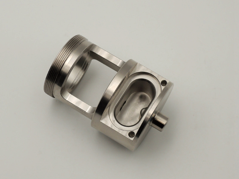
Controlling geometry in complex CNC parts involves a combination of high-precision equipment, strategic fixturing, intelligent tool path programming, and rigorous quality inspection. Whether producing aerospace turbine components, medical housings, or multi-axis machined enclosures, geometric control ensures the part meets dimensional and functional design intent.
Key Techniques for Geometric Control
Multi-Axis CNC Machining
Using 4-axis and 5-axis CNC machines allows for continuous rotation and positioning, enabling access to multiple faces in a single setup.
Reduces part repositioning, which minimizes dimensional stack-up errors and ensures consistent geometric relationships.
High-Precision Tool Paths
CAM software generates tool paths based on 3D CAD models with compensation for cutter diameter, lead-in/out, and entry angles.
Adaptive toolpaths maintain constant load, minimizing tool deflection—critical for fine geometry and thin-walled features.
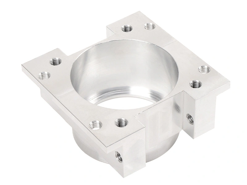
Custom Workholding and Fixturing
Fixtures are designed to locate parts using precise datums to maintain position repeatability.
Vacuum fixtures, soft jaws, and modular vises are common for non-standard geometries.
Thermal and Mechanical Compensation
CNC machines equipped with thermal compensation sensors automatically adjust for heat-induced dimensional drift.
Tool wear compensation is also programmed to maintain size control in long production runs.
In-Process Inspection
Touch probes on the machine perform automatic measurements between operations.
Real-time feedback ensures mid-process adjustments to prevent geometric deviation.
Post-Machining Verification with CMM
A coordinate measuring machine (CMM) inspects 3D geometry against the CAD model using multiple axes of measurement.
GD&T callouts (flatness, roundness, true position, etc.) are evaluated per customer drawings.
Geometric Accuracy Standards
For complex parts, manufacturers typically follow ISO 2768 or ASME Y14.5 standards. At Neway, we routinely achieve:
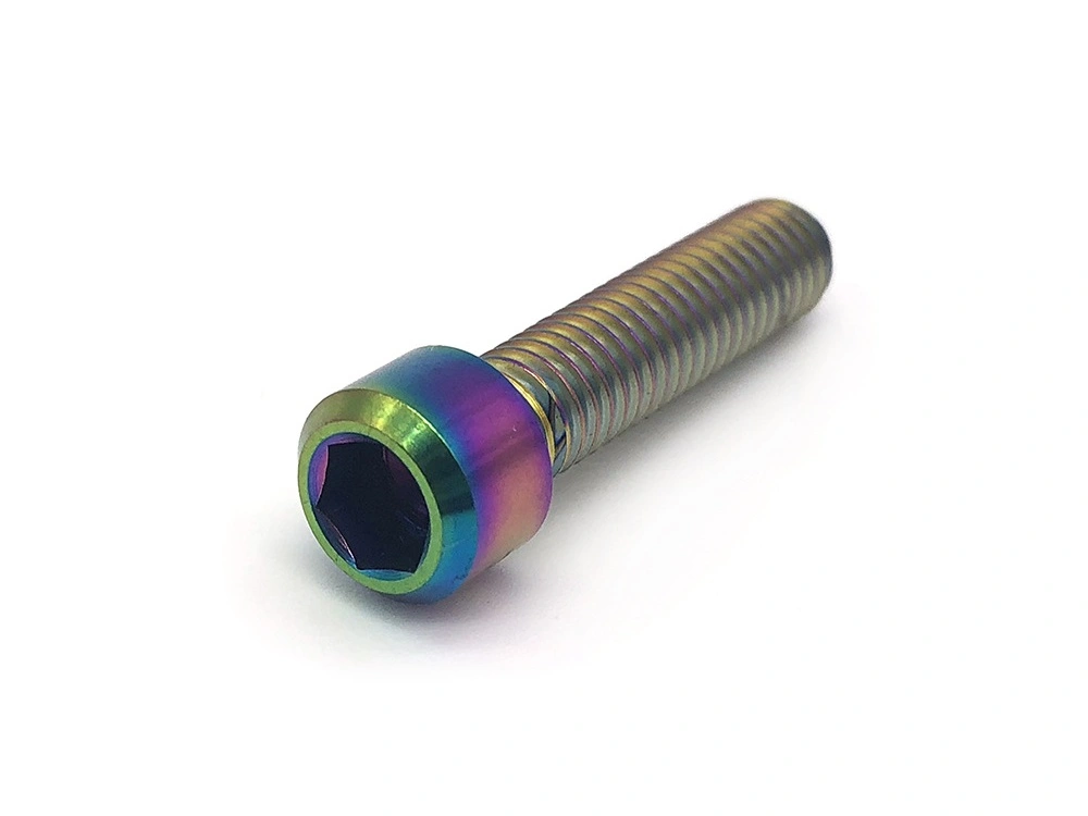
Positional tolerances: ±0.01 mm
Flatness and perpendicularity: <0.02 mm
True position and concentricity per GD&T drawings
Integrated Machining and Quality at Neway
Neway’s production process integrates precision CNC machining, advanced fixturing, and CNC prototyping with full inspection using CMM and surface metrology. This ensures geometry control in even the most complex aerospace, medical, and high-performance components.
Explore our advanced capabilities: