
Crankshaft Journal Machining With Datum Workholding and Runout Control
Crankshaft Journal Machining With Datum Workholding and Runout Control
Crankshaft journal machining depends on keeping each bearing surface in the correct relationship to the main axis while the shaft changes shape and stiffness during cutting. An accurate diameter does not establish the position of an offset crankpin. From a Neway engineering perspective, the process review should therefore begin with the drawing datum scheme, the surfaces available for locating and support, and the sequence in which those surfaces are established. The following principles explain that planning problem without prescribing one fixture or machine for every crankshaft.
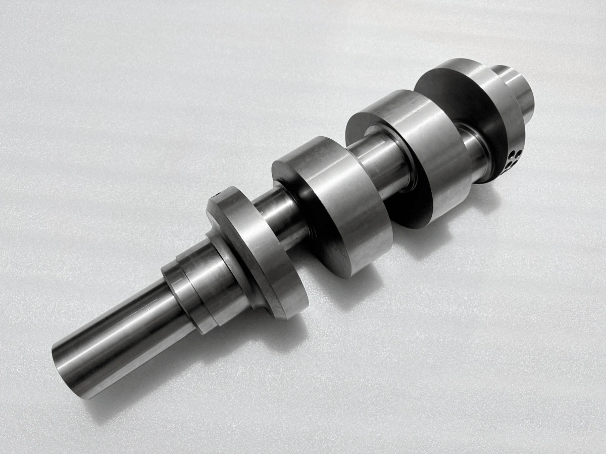
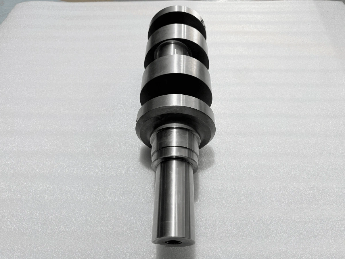
Separate the Main Axis From Crankpin Location
The main journals establish the intended rotational axis through the bearing arrangement. Each crankpin has its own nominal axis, parallel to and displaced from that main axis in a conventional crankshaft design. Its radial offset, angular phase and axial position describe different relationships. A machining plan must preserve all of them; achieving the crankpin diameter alone leaves its location unresolved.
Do not treat the intended crankpin offset as unwanted journal runout. The offset creates the crank motion, whereas a runout requirement limits variation relative to the specified datum axis on a designated surface. Read the drawing before deciding which surface should rotate concentrically during a particular setup. This distinction prevents an operator from correcting a deliberate eccentric feature toward the wrong reference.
Keep Datum Transfers Explicit
A drawing datum is a reference established from specified features, not simply the coordinate origin entered into a machine. A manufacturing setup may locate on center holes, a prepared journal or another accessible feature, but that working reference must have a controlled relationship to the drawing datum. Record that relationship in the setup plan instead of assuming that all concentric-looking surfaces share an axis.
When the shaft is reversed or moved to another operation, axial location and angular orientation need to transfer with the radial reference. A clean seating face can establish an axial stop, while an appropriate locating feature can preserve phase. Burrs, damaged centers or debris under a locator can change the setup even when the program is unchanged. Check the located condition after clamping and before removing the remaining correction stock.
Choose the Cutting Route Around the Offset Geometry
Concentric main journals are natural candidates for CNC turning. An offset crankpin needs a route that generates a cylinder about its displaced axis. Depending on the geometry and equipment, this may involve an eccentric turning setup, dedicated crankshaft milling, or coordinated machining on a suitable multi-axis platform. Tool access near the webs and fillets can rule out an otherwise plausible approach.
For eccentric turning, evaluate the rotating workpiece and fixture together. Clearance, overhang, loading and the machine's permitted operating conditions matter when the center of mass is displaced from the spindle axis. In milling, changing engagement around the crankpin places different demands on the tool and support. Select the method from the actual drawing and machine capability; a generic process name does not establish that a setup is safe or sufficiently rigid.
Support the Shaft Without Bending It Into Position
The shaft becomes less rigid as stock is removed between journals and webs. Cutting force applied far from a support can deflect a slender region, changing the diameter or form produced under load. Short tool overhang and support close to the active cut can improve stability, provided the support does not obstruct the tool path or damage a functional surface.
More clamping force is not automatically better. Excessive or uneven restraint can hold the shaft in a deflected condition that disappears when the fixture is released. Establish support contact on suitable prepared surfaces, check alignment and use a controlled clamping sequence. A steady rest should support the intended axis rather than push an incorrectly located journal into line. Compare the released condition where necessary before committing to the next finishing cut.
Use Stock Removal to Manage Changing Stiffness
A billet or forging can contain residual stresses before machining begins. Removing material redistributes those stresses and changes the section that resists cutting loads. Roughing one region heavily while leaving another untouched can therefore change the geometry available for subsequent locating. Plan roughing in stages and review the remaining stock distribution as the shaft approaches its final form.
Balanced removal is a planning principle, not a promise of zero distortion. The blank condition, feature arrangement and support access determine the practical sequence. Preserve finishing stock on surfaces whose position may change, and reassess the datum relationship after substantial removal. If stress relief is proposed, its suitability must be checked against the material condition and approved treatment route. Do not insert an unapproved thermal operation as a universal remedy.
Use Runout Trends to Investigate the Process
An intermediate runout reading is useful only when the reference, support arrangement, measurement location and part condition are known. A change after reclamping may point toward seating or locating; a change after heavy cutting may require investigation of deflection or stress redistribution. These are diagnostic leads, not conclusions established by one indicator reading.
Compare like conditions before changing offsets. Clean the locating surfaces, check support contact and confirm that the same datum relationship is being evaluated. Circularity, surface damage and the setup can all contribute to an observed indicator variation. Avoid compensating a program for what is actually a locating problem. Keep the intermediate check focused on whether the next operation can still produce the required relationship with the stock remaining.
Plan the Finishing Reference Before Roughing Is Complete
If the route includes CNC grinding, decide early how the finishing operation will recover the intended axis and crankpin location. Grinding can finish a bearing surface only within the material available and the approved process constraints. A small diameter allowance cannot be assumed sufficient to correct a large positional error.
Where heat or surface treatment separates machining stages, reassess the relevant locating features afterward. Specify whether the retained allowance is radial or diametral and which dimensions apply at each handover. The final reference must remain consistent with the drawing, even if a different machine or support arrangement is used. Detailed grinding, hardness and final inspection questions are addressed separately in the linked FAQs.
Define the Setup Questions in the RFQ
For a crankshaft journal machining review, send Neway the controlled drawing and model, material delivery condition, required quantity and final treatment requirements. Identify the main datum features, crankpin offsets and phase relationships, surfaces that may be used for support, and any restrictions on temporary locating features. Ask for the proposed setup sequence and intermediate checks before approving production. This gives the engineering discussion a practical focus: how each operation will preserve the geometry needed by the next.
FAQ
